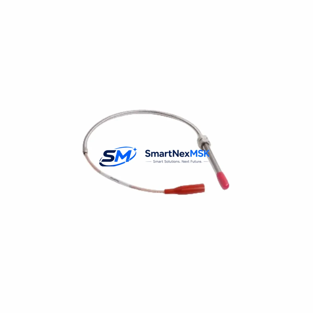
PROVIBTECH TM0180-A08-B00-C12-D10 Retrofit-Ready Proximity Probe for TM Series Control Systems
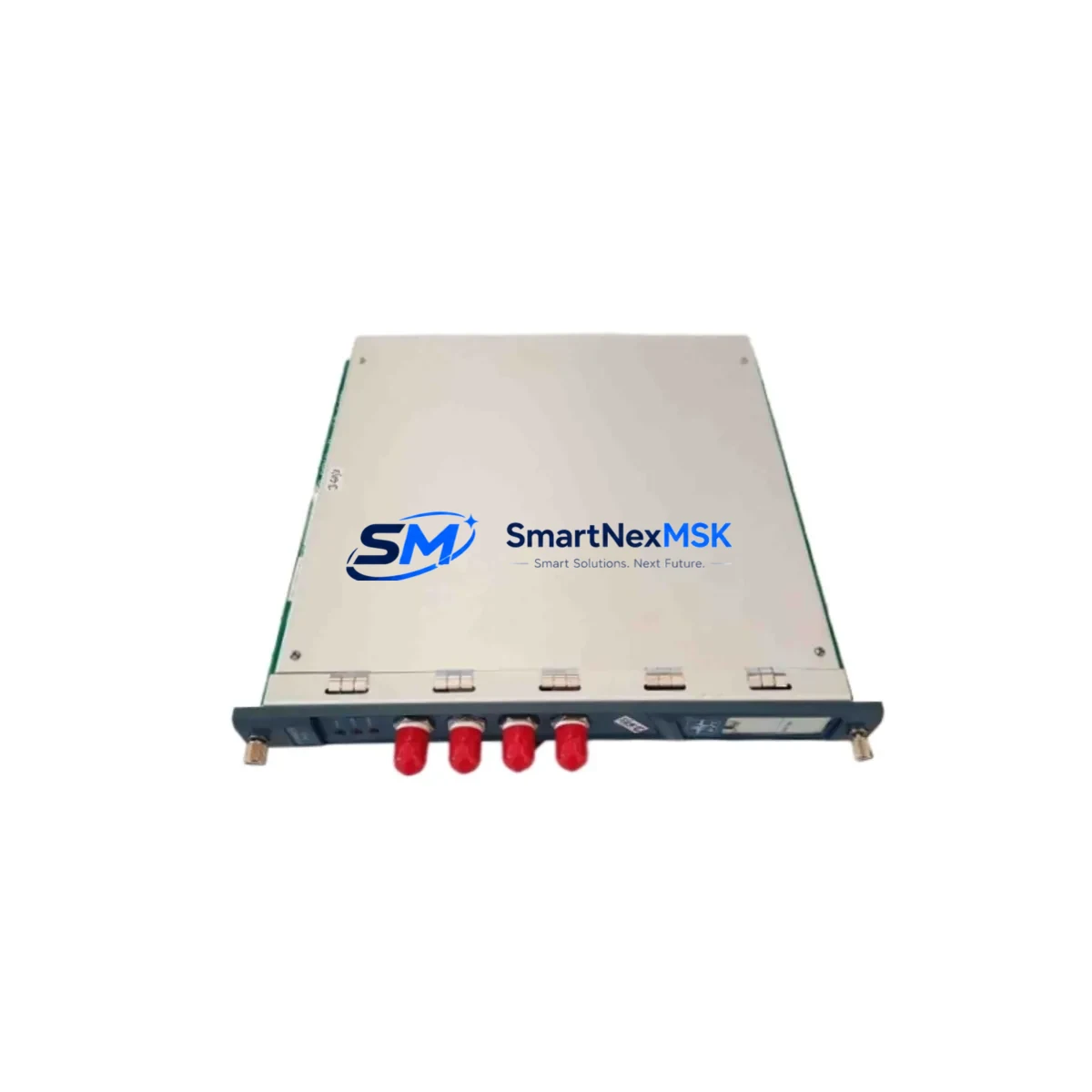
The PROVIBTECH TM0180-A08-B00-C12-D10 is an eddy-current proximity probe engineered for seamless integration into legacy vibration monitoring and machinery protection systems. Designed as a direct retrofit replacement within the PROVIBTECH TM Series platform, this probe supports aging infrastructure upgrades, discontinued spare part substitution, and full-system modernization projects without requiring changes to existing signal conditioning chains or DCS/PLC interface wiring.
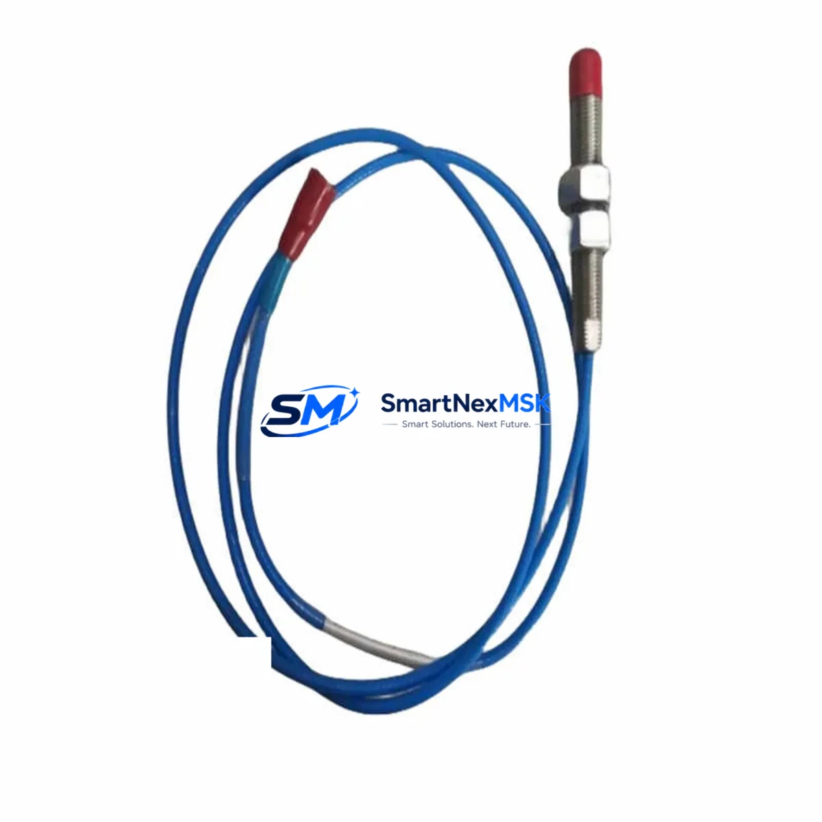
With an 8 mm probe tip diameter, 12 mm linear measurement range, and a standard 5-meter extension cable interface, the TM0180-A08-B00-C12-D10 maintains full electrical and mechanical compatibility with the PROVIBTECH TM0180 driver/oscillator family. Engineers undertaking control cabinet upgrades or machinery protection panel retrofits can install this probe without modifying the existing TM0180 proximitor housing, terminal block assignments, or 4–20 mA output loop wiring connected to downstream safety PLCs or condition monitoring systems.
Upgrade Compatibility Table
| Parameter | TM0180-A08-B00-C12-D10 | Retrofit Notes |
|---|---|---|
| Probe Tip Diameter | 8 mm | Matches standard TM Series mounting bore; no machining required |
| Linear Range | 12 mm (0.5 in) | Compatible with existing gap-setting procedures on TM0180 driver |
| Extension Cable Length | 5 m (standard) | Verify cable routing length before ordering; custom lengths available |
| Driver/Oscillator Compatibility | PROVIBTECH TM0180 Series | Do not mix with non-matched drivers; system sensitivity will shift |
| Output Signal | –24 VDC / mV/mil standard | Confirm DCS/PLC input card scaling before commissioning |
| Installation Interface | Threaded probe body, standard TM Series bracket | Reuse existing mounting hardware; inspect threads for wear |
| Communication Compatibility | Analog (4–20 mA / voltage) | Compatible with PROVIBTECH TM Series monitor cards and third-party vibration monitors |
| Replacement Recommendation | Direct drop-in for discontinued TM0180-A08 variants | Confirm A/B/C/D suffix codes match original order specification |
| Commissioning Focus | Gap voltage, sensitivity calibration, alarm setpoint verification | Use original OEM gap-setting tool or equivalent calibrated spacer |
| Warranty | 12 Months | Covers manufacturing defects; excludes physical damage from installation |
Retrofit Planning for Existing Automation Systems
Successful integration of the TM0180-A08-B00-C12-D10 into an existing machinery protection or condition monitoring system requires a structured pre-installation audit. Before removing the legacy probe, engineers should document the current gap voltage reading at the TM0180 proximitor output terminal — typically measured between the COM and OUT terminals on the driver housing — and record the baseline vibration amplitude and DC gap values displayed on the associated PROVIBTECH TM Series monitor card or the plant DCS historian.
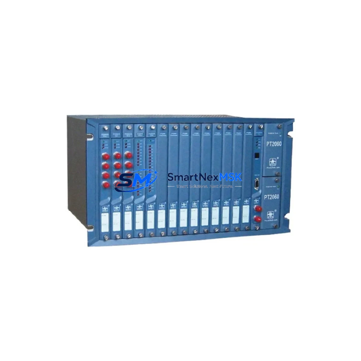
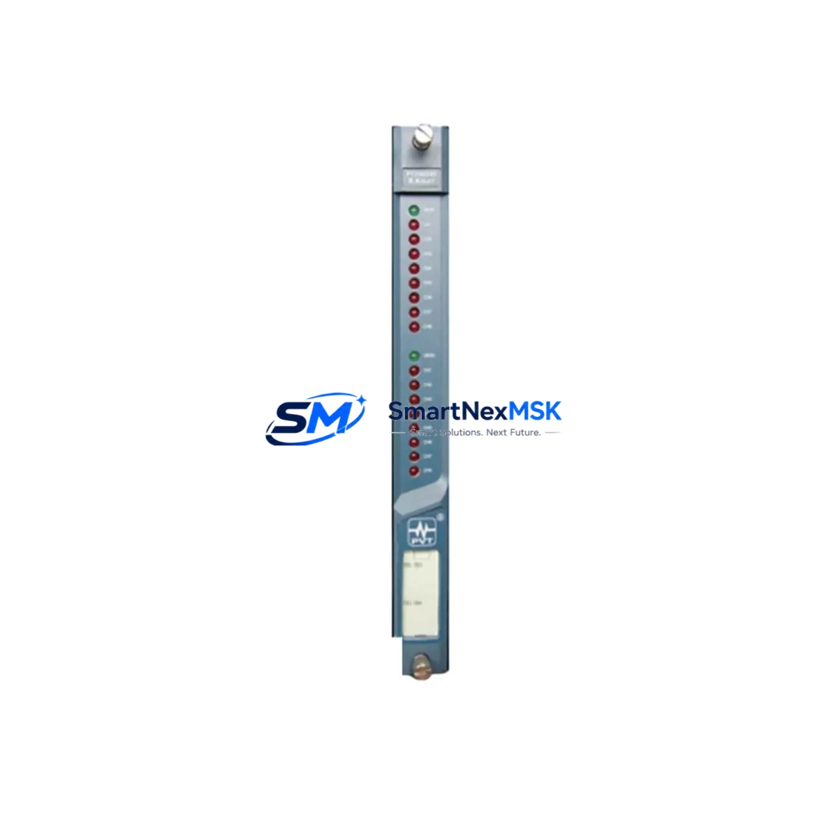
In systems where the TM0180 driver feeds a PROVIBTECH TM0182 or TM0183 dual-channel vibration monitor, the channel inhibit function should be activated prior to probe removal to prevent spurious trip signals from propagating to the safety PLC or emergency shutdown system. For plants running a PROVIBTECH TM0100 rack-mounted monitoring system, the relevant I/O module slot should be placed in bypass mode through the system configuration software before any field wiring is disturbed.
Terminal block wiring for the TM0180-A08-B00-C12-D10 follows the standard three-conductor shielded cable scheme: power (–24 VDC), common (COM), and output (OUT). When replacing probes in a multi-channel cabinet that also houses a PROVIBTECH TM0190 keyphasor probe or a TM0181 thrust position probe, care must be taken to maintain cable shield grounding continuity at the proximitor end only — grounding at both ends introduces ground loops that corrupt the vibration signal baseline.
For systems undergoing a broader platform migration — for example, transitioning from a standalone PROVIBTECH TM Series rack to an integrated Bently Nevada 3500-compatible monitoring architecture — the TM0180-A08-B00-C12-D10 can serve as an interim field sensor while the monitor cards and I/O backplane are upgraded in stages. This phased approach allows production to continue on unaffected machine trains while the new monitoring infrastructure is commissioned loop by loop.
Where the existing control cabinet includes a PROVIBTECH TM0300 series communication gateway or a Modbus RTU interface module connecting vibration data to a SCADA or DCS historian, the probe replacement itself does not affect the communication link — only the analog signal chain from field to monitor card is interrupted during the swap. Confirm that the SCADA tag for the affected channel is placed in manual or suppressed mode in the DCS configuration to avoid false alarms during the gap-setting procedure.
All replacement probes are shipped pre-tested and include a factory calibration certificate. Each unit undergoes sensitivity verification against the matched TM0180 driver before dispatch, ensuring the probe-driver system meets the original OEM sensitivity specification (typically 7.87 V/mm or 200 mV/mil) within ±1% tolerance. Stock is maintained for immediate dispatch, supporting urgent breakdown maintenance and planned turnaround outages with equal reliability.
Downtime Control During System Migration
Minimizing unplanned downtime during a proximity probe replacement is a function of preparation, not speed. The most effective strategy is to pre-stage the replacement TM0180-A08-B00-C12-D10 probe and its matched extension cable at the work site before the machine is taken offline, with the gap-setting tool, a calibrated digital multimeter, and the original commissioning sheet for the channel in hand.
Where the machine protection system permits hot-swap of individual probe channels — common in dual-redundant configurations using two TM0180 drivers feeding a voting monitor — the replacement can be performed with the machine at reduced load rather than full shutdown. In single-channel configurations, the machine must be stopped, but the control program logic in the safety PLC or DCS does not need to be modified: the channel simply returns to service after the new probe is gapped and the output voltage is verified within the alarm-free window defined in the original system design.
Original program logic, HMI faceplate configurations, and historian tag assignments remain fully intact throughout the probe replacement process. No PLC program download, HMI screen rebuild, or DCS database modification is required when replacing a like-for-like TM0180-A08-B00-C12-D10 unit. This is a key advantage of sourcing a matched replacement rather than attempting to adapt a probe from a different manufacturer or series, which would require sensitivity recalibration, alarm setpoint recalculation, and potentially a management-of-change review under the plant’s process safety management program.
After installation, the commissioning sequence is straightforward: power the proximitor, measure the DC gap voltage at the driver output terminal, adjust the probe axial position until the gap voltage falls within the specified linear range center (typically –10 VDC ±0.5 V for a 1 mm nominal gap), tighten the locknut, and verify the vibration amplitude reading on the monitor card matches the pre-outage baseline within acceptable tolerance. Total field time for an experienced technician is typically under 45 minutes per channel.
Retrofit Support FAQ
Q1: Is the TM0180-A08-B00-C12-D10 a direct replacement for my existing TM0180 probe, and do I need to recalibrate the driver?
A: Yes — provided the suffix codes (A08, B00, C12, D10) match your original probe specification, the TM0180-A08-B00-C12-D10 is a direct drop-in replacement. The matched TM0180 driver does not require recalibration; however, you must re-gap the probe in the field and verify the output DC voltage falls within the driver’s specified linear range before returning the channel to service.
Q2: Can I use this probe with a non-PROVIBTECH vibration monitor or a third-party DCS input card?
A: The TM0180-A08-B00-C12-D10 outputs a standard eddy-current proximity probe signal (–24 VDC supply, mV/mil sensitivity) compatible with most third-party vibration monitors that accept industry-standard proximity probe inputs. Confirm the input card’s supply voltage range and sensitivity scaling before connecting. If the monitor expects a different sensitivity (e.g., 100 mV/mil vs. 200 mV/mil), alarm setpoints must be recalculated accordingly.
Q3: What wiring checks should I perform before powering up the replacement probe?
A: Verify three items before energizing: (1) cable shield is grounded at the proximitor end only; (2) the –24 VDC supply line is within ±10% of nominal at the driver terminal under load; and (3) the extension cable connector is fully seated and the locking collar is finger-tight. A loose connector is the most common cause of intermittent signal dropout after probe replacement.
Q4: What does the 12-month warranty cover, and how is a warranty claim processed?
A: The 12-month warranty covers manufacturing defects in materials and workmanship from the date of shipment. It does not cover damage resulting from incorrect installation, over-range mechanical contact, or use with a mismatched driver. To initiate a warranty claim, contact sales@smartnexmsk.com with the order number, probe serial number, and a description of the fault. Replacement units are dispatched after fault verification, with return shipping of the defective unit required.
© 2026 SMARTNEXMSK. All rights reserved.
Original Source: https://smartnexmsk.com
Contact: sales@smartnexmsk.com | +86 18259474341