PROVIBTECH TM0181-A40-B01 Retrofit-Ready Vibration Transmitter for TM Series Control Systems
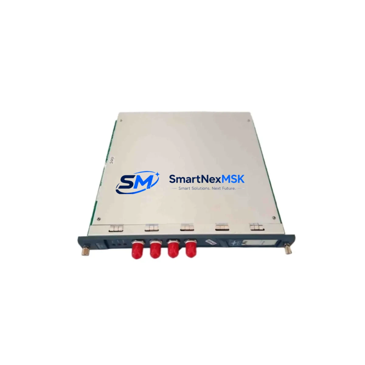
The PROVIBTECH TM0181-A40-B01 is a loop-powered, 4–20 mA vibration transmitter engineered for seamless integration into TM Series condition monitoring architectures. As legacy vibration monitoring systems approach end-of-life or face discontinued spare parts availability, the TM0181-A40-B01 provides a verified drop-in retrofit path that preserves existing wiring infrastructure, DCS signal loops, and PLC input card assignments — minimizing engineering rework and unplanned downtime during system modernization.
Designed for industrial environments where continuous machine health monitoring is non-negotiable, this transmitter delivers reliable broadband vibration measurement across rotating equipment including pumps, compressors, fans, and turbines. Its two-wire, loop-powered design eliminates the need for separate power supply wiring, making it directly compatible with existing 4–20 mA input channels on distributed control systems and standalone condition monitoring racks.
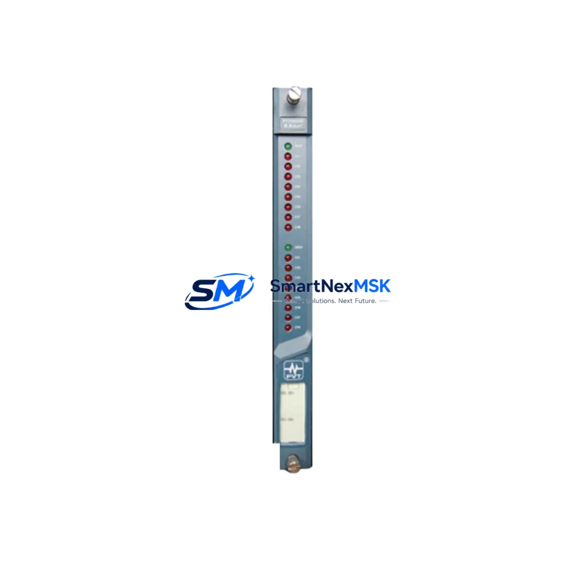
For facilities currently operating PROVIBTECH TM Series transmitters — including models such as the TM0181-A40-B00 and TM0181-A20-B01 — the TM0181-A40-B01 offers a direct functional replacement with no firmware changes required at the DCS or PLC level. Engineers migrating from older TM Series variants should verify terminal block pinout compatibility and confirm that the existing TM Series signal conditioner or barrier module supports the updated transmitter’s output impedance range before commissioning.
Upgrade Compatibility Table
| Parameter | TM0181-A40-B01 (This Unit) | Retrofit Notes |
|---|---|---|
| Output Signal | 4–20 mA (2-wire loop-powered) | Compatible with existing 4–20 mA DCS/PLC input cards |
| Measurement Range | 0–40 mm/s RMS (velocity) | Verify DCS scaling — update engineering units if replacing A20 variant |
| Power Supply | 18–30 VDC (loop-supplied) | Confirm barrier/isolator output voltage meets minimum 18 VDC under load |
| Connector / Terminal | 2-pin terminal block (standard TM Series) | Direct pin-for-pin replacement; no rewiring required for same-series swap |
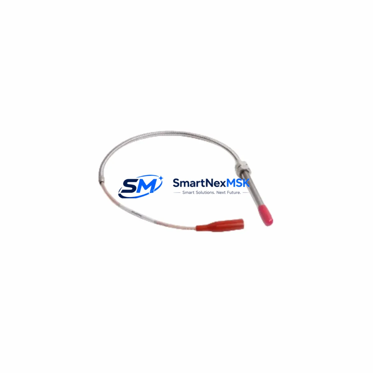
| Mounting Interface | M8 × 1.25 stud mount | Compatible with existing TM Series mounting pads and adapters |
| Communication Protocol | Analog 4–20 mA (HART-passive) | No protocol migration required; HART overlay possible with compatible master |
| Replacement Compatibility | TM0181-A40-B00, TM0181-A20-B01 (with range check) | Confirm DCS input range scaling before live cutover |
| Commissioning Requirement | Zero-point verification, loop calibration check | Use portable calibrator on 4–20 mA loop before returning to service |
| Warranty | 12 Months | Covered from date of shipment; includes functional test certificate |
Retrofit Planning for Existing Automation Systems
Successful integration of the TM0181-A40-B01 into an operating plant begins well before the physical swap. A structured retrofit plan should address the full signal chain from sensor to control room, ensuring that every component in the measurement loop is verified for compatibility.
Start by auditing the existing TM Series junction box or field terminal assembly. Confirm that the two-wire cable gauge and insulation rating are appropriate for the loop current range and ambient temperature at the installation point. In most TM Series installations, the existing cable infrastructure can be reused without modification, which significantly reduces retrofit labor costs.
At the control cabinet level, verify that the DCS analog input module — commonly a 4–20 mA input card from the site’s existing control platform — is configured for the correct engineering unit range. If the previous transmitter was a TM0181-A20-B01 (0–20 mm/s range) and the replacement is the A40 variant (0–40 mm/s range), the DCS input scaling must be updated in the controller configuration before the new transmitter is energized. Failure to update the scaling will result in incorrect vibration readings and may trigger false alarms on the condition monitoring HMI or historian.
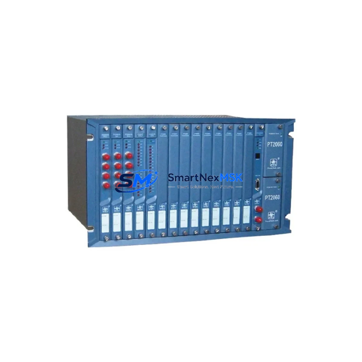
For sites using a PROVIBTECH TM Series rack-mounted signal conditioner or a standalone vibration monitoring relay module, confirm that the relay trip setpoints are recalibrated to reflect the new full-scale range. This is particularly important in applications where the vibration transmitter output feeds directly into a machinery protection system with hardwired trip logic.
Where the TM0181-A40-B01 is being installed as part of a broader control system upgrade — for example, alongside a new PLC remote I/O module or an upgraded HART multiplexer — coordinate the transmitter commissioning with the I/O module address assignment and tag database update. Ensure that the new transmitter tag is correctly mapped in the asset management software and that the historian is configured to log the new engineering unit range from the first scan cycle.
In multi-machine installations, it is common to replace several TM Series transmitters simultaneously. In these cases, a portable vibration calibrator or loop calibrator should be used to inject a known 4–20 mA signal at the field terminal and verify end-to-end signal integrity before the machine is returned to service. Document the as-found and as-left readings for each transmitter as part of the site’s maintenance record.
For applications where the vibration transmitter feeds a wireless HART adapter or a fieldbus gateway, confirm that the gateway’s polling configuration is updated to reflect the new transmitter tag and measurement range. This step is frequently overlooked during rapid retrofit campaigns and can result in data gaps in the plant historian.
Downtime Control During System Migration
Minimizing production downtime during a vibration transmitter retrofit requires a disciplined pre-outage preparation process. All configuration changes — DCS scaling updates, HMI faceplate range adjustments, historian tag modifications, and alarm setpoint reviews — should be completed and validated in the control system’s offline simulation environment before the planned maintenance window begins.
During the physical swap, isolate the 4–20 mA loop at the field junction box rather than at the DCS cabinet to preserve the integrity of the control room wiring. Label the disconnected terminals clearly and photograph the as-found wiring configuration before removing the old transmitter. The TM0181-A40-B01’s direct terminal compatibility with the TM Series standard means that reconnection is straightforward, but a second technician should verify polarity before the loop is re-energized.
Once the new transmitter is installed and the loop is re-energized, perform a live loop check by observing the DCS analog input reading while the machine is at rest (expected output: approximately 4 mA, corresponding to 0 mm/s). If the machine cannot be safely run at zero vibration for the check, use a loop calibrator to inject 4 mA and 20 mA signals at the field terminal and confirm that the DCS displays 0 mm/s and 40 mm/s respectively. This two-point verification confirms both the transmitter output and the DCS scaling are correctly aligned before the machine is returned to automatic control.
For critical machinery where continuous monitoring cannot be interrupted, consider using a portable vibration data collector in parallel during the cutover window to maintain a manual monitoring record until the new transmitter is confirmed in service. This approach is particularly valuable in compressor and turbine applications where the machinery protection system relies on the 4–20 mA signal for automatic trip logic.
After the transmitter is confirmed in service, update the plant’s preventive maintenance schedule and spare parts register to reflect the new model number. Retain the replaced transmitter for bench testing if the unit is being returned under warranty evaluation, or dispose of it in accordance with the site’s electronic waste policy.
Retrofit Support FAQ
Q1: Is the TM0181-A40-B01 a direct drop-in replacement for the TM0181-A40-B00?
A: Yes. The TM0181-A40-B01 is the current production revision of the TM0181-A40-B00 and is electrically and mechanically interchangeable. The terminal pinout, mounting thread, and 4–20 mA output range are identical. No wiring changes or DCS reconfiguration are required when replacing a B00 suffix unit with a B01 suffix unit.
Q2: What pre-shipment testing is performed on the TM0181-A40-B01?
A: Each unit undergoes a full functional test prior to shipment, including loop output verification across the 4–20 mA range, insulation resistance check, and vibration sensitivity calibration. A test certificate is available upon request. The 12-month warranty covers manufacturing defects and functional failures under normal operating conditions from the date of shipment.
Q3: Can the TM0181-A40-B01 be used with a HART-enabled DCS input card?
A: The TM0181-A40-B01 outputs a standard 4–20 mA analog signal. While it does not actively transmit HART digital data, it is passive-HART compatible, meaning a HART master device can be connected in parallel on the loop without interfering with the analog signal. Confirm with your DCS vendor that the input card supports passive HART overlay before enabling HART polling.
Q4: What should I check if the DCS reads a fixed 4 mA after installation?
A: A fixed 4 mA output at rest is normal when the machine is stationary. If the reading remains at 4 mA during machine operation, check the following in sequence: (1) confirm loop supply voltage at the transmitter terminals is ≥18 VDC under load; (2) verify that the cable shield is grounded at one end only to avoid ground loop interference; (3) confirm the transmitter mounting stud is making firm contact with the machine surface — poor mechanical coupling is the most common cause of unexpectedly low vibration readings after a retrofit installation.
© 2026 SMARTNEXMSK. All rights reserved.
Original Source: https://smartnexmsk.com
Contact: sales@smartnexmsk.com | +86 18259474341