SANYO DENKI PYRG015K1XXVP00 Spare PY Series Automation: Spare Replacement & Industrial Downtime Risk Control
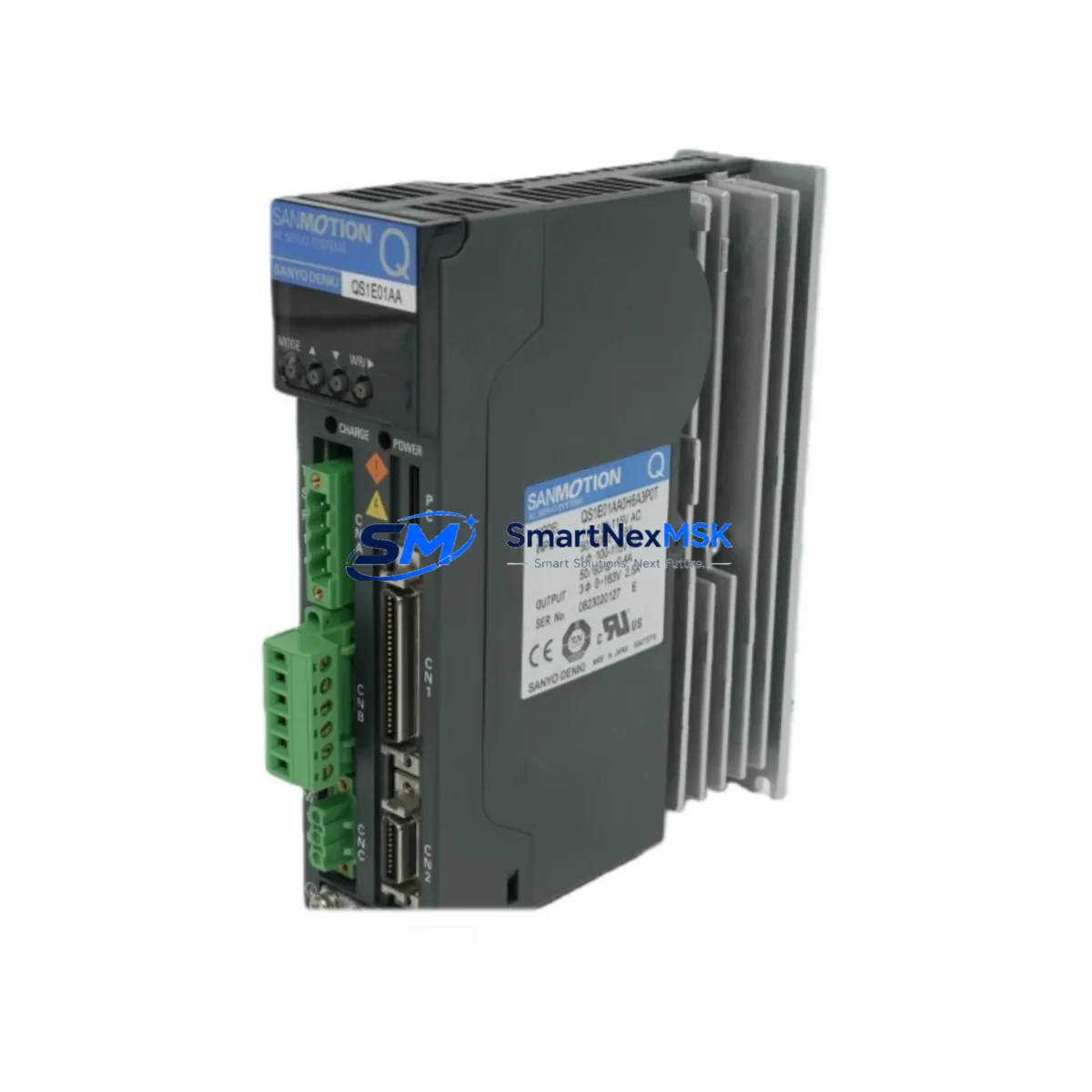
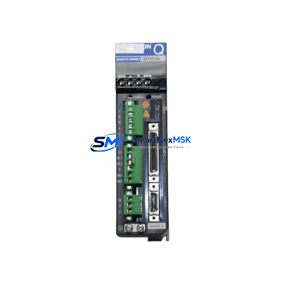
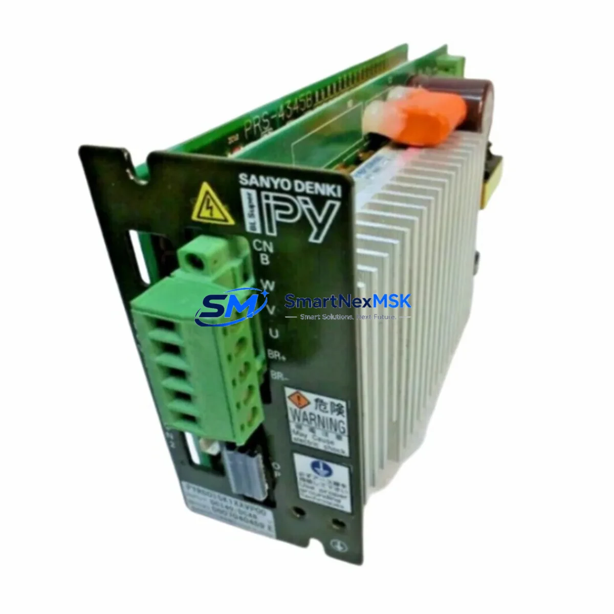
The SANYO DENKI PYRG015K1XXVP00 is a PY Series AC servo amplifier designed for precision motion control in demanding industrial automation environments. As a maintenance-ready original spare, this unit supports rapid fault isolation and system restoration — minimizing unplanned downtime in servo-driven production lines, CNC machining centers, packaging equipment, and multi-axis robotic cells. Whether you are executing a planned overhaul, responding to an emergency drive failure, or building a strategic spare parts inventory, the PYRG015K1XXVP00 delivers verified compatibility and reliable performance from day one of installation.
Maintenance engineers and procurement teams working with SANYO DENKI PY Series systems recognize that servo amplifier failures rarely occur in isolation. A failed PYRG015K1XXVP00 often signals stress across adjacent components in the same control cabinet — making a structured replacement workflow and a well-stocked spare parts list essential for sustained uptime.
Spare Maintenance Table
| Parameter | Specification / Detail |
|---|---|
| Part Number / SKU | PYRG015K1XXVP00 |
| Brand | SANYO DENKI |
| Series | PY Series |
| Product Type | AC Servo Amplifier |
| Applicable Motor Series | SANYO DENKI PY Series Servo Motors |
| Control Mode | Position / Speed / Torque (multi-mode) |
| Input Power | Three-phase / Single-phase AC (per series spec) |
| Communication Interface | Pulse train, analog reference; optional fieldbus per variant |
| Encoder Compatibility | PY Series incremental / absolute encoders |
| Mounting | DIN rail / panel mount, standard PY Series footprint |
| Operating Temperature | 0°C to 55°C (storage: -20°C to 65°C) |
| Origin | Japan |
| Condition | Original spare — new or reconditioned to OEM spec |
| Pre-shipment Testing | Functional test performed before dispatch |
| Warranty | 12 Months |
| Delivery | Worldwide; expedited options available |
| Maintenance Recommendation | Inspect cooling fan, encoder cable, and regenerative resistor at replacement |
Maintenance Planning for Continuous Operation
When replacing the PYRG015K1XXVP00 servo amplifier, a thorough inspection of the surrounding control cabinet components is strongly recommended. Servo amplifier failures are frequently preceded or accompanied by degradation in related subsystems. Maintenance engineers should verify the following during the same service window:
Power supply integrity: Check the 24 VDC control power supply feeding the amplifier’s logic section. A marginal or noisy DC supply — such as a SANYO DENKI or equivalent switching power supply module — can cause erratic amplifier behavior that mimics drive faults. Measure output voltage under load and inspect for ripple before commissioning the replacement unit.
Encoder cable and feedback wiring: The PY Series encoder cable connecting the servo motor to the PYRG015K1XXVP00 is a common wear item. Inspect the cable sheath, connector pins, and shield termination. A damaged encoder cable will generate position feedback errors immediately after amplifier replacement, leading to a misdiagnosed repeat failure.
Regenerative resistor and braking circuit: If the application involves frequent deceleration or vertical axis loads, inspect the external regenerative resistor (if fitted) for signs of overheating or open circuit. An undersized or failed regenerative resistor can cause overvoltage faults that damage a new amplifier within hours of installation.
I/O terminal block and signal wiring: Inspect the I/O terminal strip connected to the amplifier’s CN1 or equivalent connector. Loose terminals, corroded contacts, or miswired enable/inhibit signals are a frequent source of post-replacement commissioning failures. Verify servo-on, alarm reset, and limit switch signals with a multimeter before powering up.
Communication and fieldbus modules: For systems using MECHATROLINK, EtherCAT, or PROFIBUS communication cards installed in or alongside the PY Series amplifier, confirm that the communication module firmware and node address settings are preserved or correctly re-entered after replacement. A communication timeout fault will prevent the axis from accepting motion commands even if the amplifier itself is fully functional.
Safety relay and contactor: The main contactor or safety relay controlling AC power to the amplifier should be inspected for contact wear. A contactor with pitted contacts can cause intermittent power interruptions that generate nuisance faults and shorten amplifier service life. This is particularly important in high-cycle applications.
Fuses and circuit protection: Replace the input fuses or circuit breaker protecting the PYRG015K1XXVP00 as a matter of routine when swapping the amplifier. A fuse that has experienced a fault current event may have degraded without blowing, and will fail prematurely under normal operating current.
HMI and operator panel: If the machine uses a SANYO DENKI or third-party HMI for parameter display and tuning, verify that the servo parameter file (gain settings, electronic gear ratio, torque limits) is backed up and can be restored to the replacement amplifier. Parameter loss is a common cause of extended commissioning time after an emergency replacement.
Stocking the PYRG015K1XXVP00 alongside complementary spares — including a spare encoder cable assembly, a replacement 24 VDC power supply module, a set of input fuses, and a spare I/O terminal block — allows maintenance teams to resolve the majority of PY Series servo faults within a single shift, without waiting for additional parts procurement.
Site Replacement Workflow
Step 1 — Fault confirmation: Record the active alarm code displayed on the amplifier or HMI. Common PY Series fault codes include encoder errors, overcurrent, overvoltage, and communication loss. Document the fault history before powering down to guide post-replacement verification.
Step 2 — Safe isolation: Isolate AC input power at the circuit breaker and discharge the DC bus capacitors per SANYO DENKI safety guidelines. Confirm zero voltage on the DC bus terminals before handling the amplifier.
Step 3 — Parameter backup: If the amplifier is still partially functional, use the HMI or PC software to export the current parameter set. If the unit is completely failed, retrieve parameters from the machine’s maintenance logbook or backup file.
Step 4 — Physical replacement: Disconnect all connectors (power, encoder, I/O, communication) in sequence. Remove the failed PYRG015K1XXVP00 from the DIN rail or panel mount. Install the replacement unit, reconnect all connectors, and verify cable routing and shield grounding.
Step 5 — Parameter restore and commissioning: Restore the saved parameter set to the replacement amplifier. Perform a no-load jog test at low speed to confirm encoder feedback direction and basic motion response before returning the axis to full production speed.
Step 6 — System verification: Run the machine through a complete production cycle at reduced speed. Monitor amplifier status, current draw, and temperature for the first 30 minutes of operation. Confirm that no latent faults are present before returning the line to full production rate.
This structured workflow reduces mean time to repair (MTTR) and prevents secondary damage caused by rushed or incomplete replacements — a critical advantage in high-value production environments where every hour of downtime carries significant cost.
Spare Parts Support FAQ
Q1: Is the PYRG015K1XXVP00 a direct drop-in replacement for the unit currently installed in my machine?
The PYRG015K1XXVP00 is an original SANYO DENKI PY Series servo amplifier and is designed to be dimensionally and electrically compatible with other units of the same model number. Before installation, confirm that the motor model, encoder type, power supply voltage, and parameter settings match your existing configuration. If your machine uses a slightly different variant suffix, contact our technical team for compatibility confirmation before ordering.
Q2: What pre-shipment testing is performed on this spare?
Every PYRG015K1XXVP00 unit is functionally tested before dispatch. Testing covers power-on self-diagnostics, encoder interface verification, and basic motion response where applicable. A test report is available on request. The unit ships with a 12-month warranty covering manufacturing defects and functional failures under normal operating conditions.
Q3: How should I manage spare parts inventory for a multi-axis PY Series system?
For systems with three or more PY Series axes, we recommend stocking at least one PYRG015K1XXVP00 amplifier spare per machine, along with a spare encoder cable set and a 24 VDC power supply module. For critical production lines, a two-unit buffer stock reduces the risk of extended downtime during peak demand periods when lead times for new procurement may be longer than acceptable. Review your spare parts list annually and replace any unit that has been in storage for more than five years.
Q4: What is the warranty coverage and what does it include?
This spare carries a 12-month warranty from the date of shipment. The warranty covers functional failures attributable to manufacturing defects or component quality. It does not cover damage resulting from incorrect installation, parameter misconfiguration, overvoltage events caused by external circuit faults, or physical damage during handling. In the event of a warranty claim, contact our support team with the order number, fault description, and alarm code history for rapid assessment and replacement processing.
© 2026 SMARTNEXMSK. All rights reserved.
Original Source: https://smartnexmsk.com
Contact: sales@smartnexmsk.com | +86 18259474341