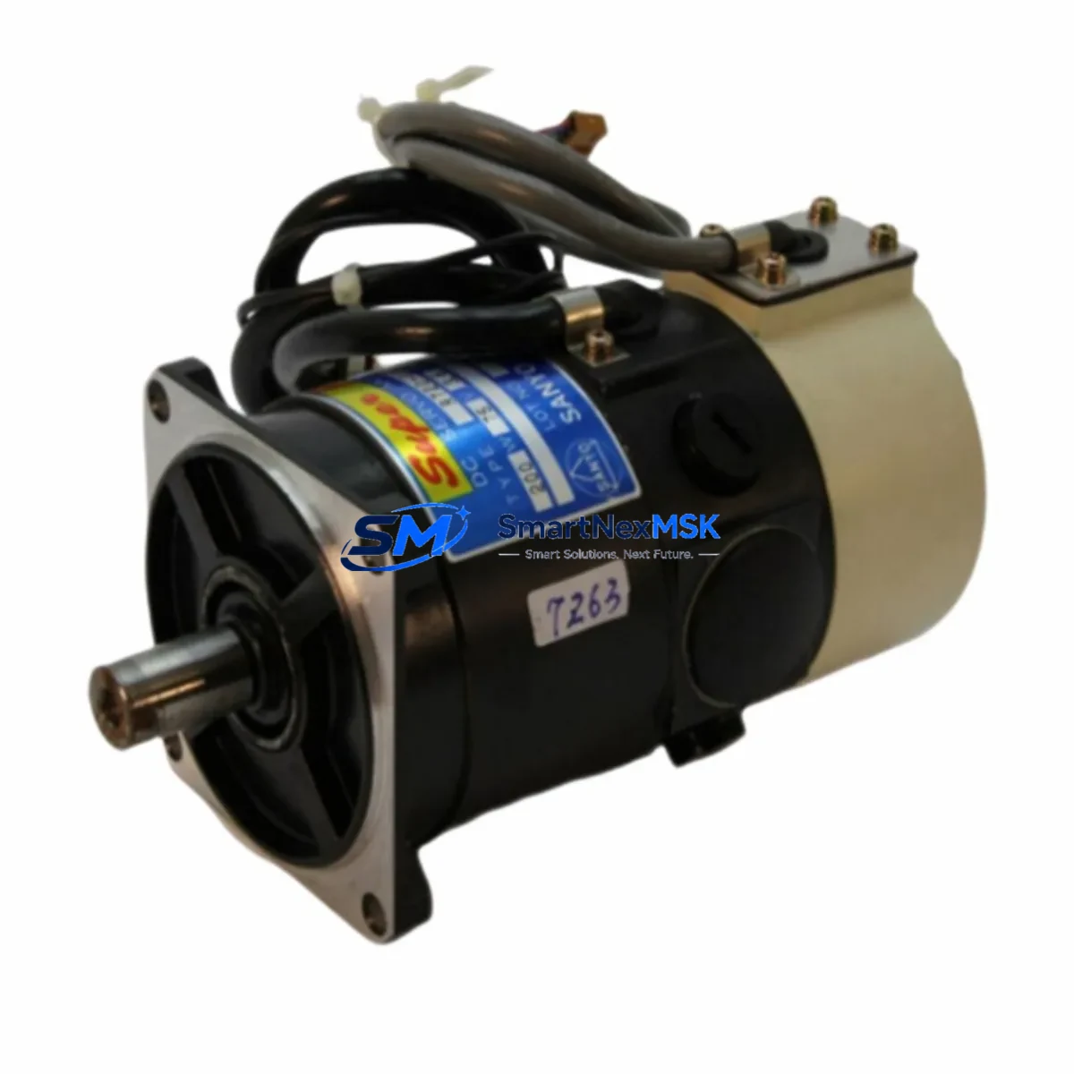
SANYO DENKI QF1PA270N1 Retrofit-Ready AC Servo Motor for Q Series Control Systems
The SANYO DENKI QF1PA270N1 is a high-performance AC servo motor engineered for seamless integration into legacy Q Series automation platforms. As industrial facilities face increasing pressure to modernize aging control infrastructure without full line shutdowns, the QF1PA270N1 has become a trusted retrofit solution for engineers replacing discontinued servo drives, upgrading motion control cabinets, and restoring production continuity on lines originally built around SANYO DENKI Q Series architecture.
Whether you are replacing a failed unit on an active production line, sourcing a long-lead discontinued part for a scheduled maintenance window, or planning a phased upgrade of your servo axis configuration, the QF1PA270N1 delivers the mechanical and electrical compatibility required to minimize engineering rework. Its encoder interface, shaft dimensions, and mounting flange conform to Q Series mechanical standards, allowing direct substitution without custom adapter plates or motor bracket modifications in most installations.
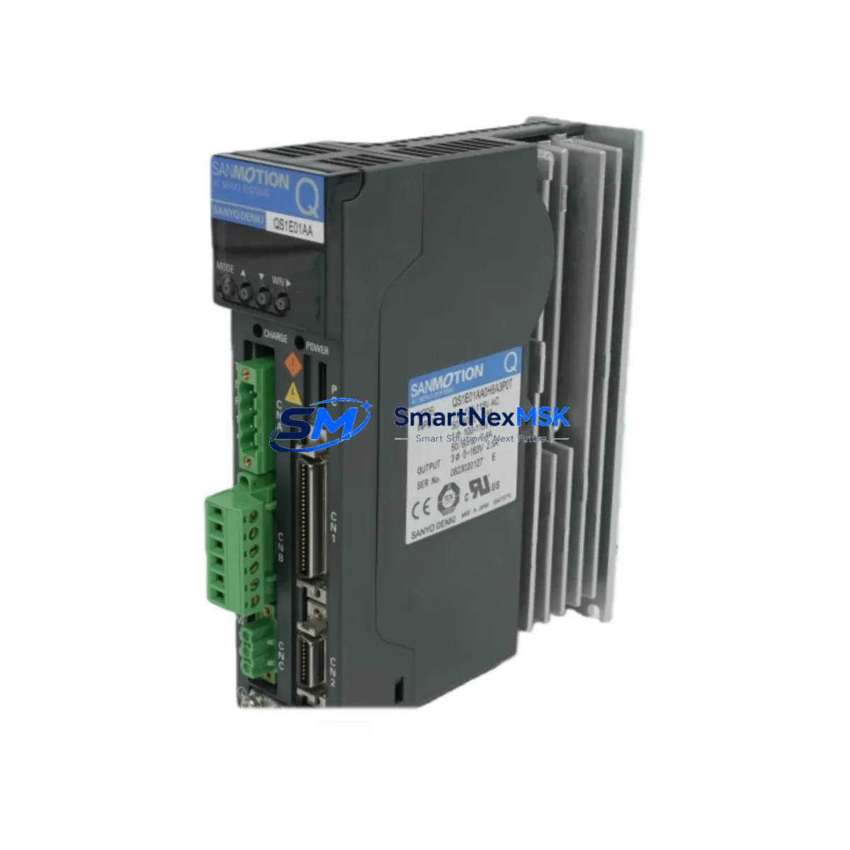
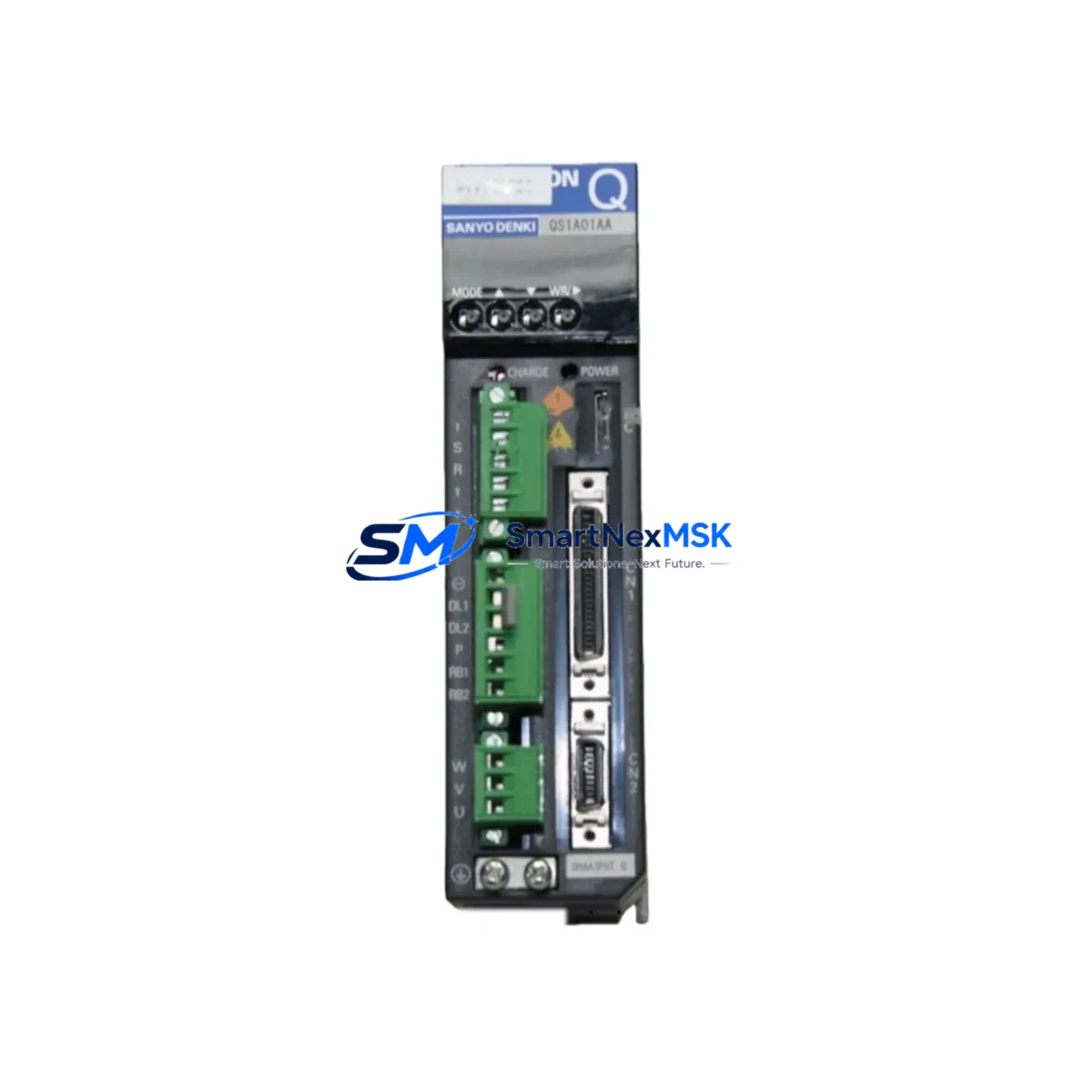
Before committing to installation, engineers should verify several critical parameters. Power supply capacity at the servo amplifier — typically a SANYO DENKI RS2 Series or compatible drive — must be confirmed against the QF1PA270N1 rated current draw to avoid nuisance tripping or drive fault conditions. Terminal block wiring should be cross-referenced against the original motor’s connector pinout; while the QF1PA270N1 maintains Q Series signal compatibility, encoder cable shielding and ground continuity must be inspected and re-terminated if the original cable shows insulation degradation. Backplane interface assignments and axis address configuration within the motion controller should be documented prior to removal of the legacy unit to ensure the replacement motor is recognized correctly by the PLC or CNC controller on first power-up.
Program compatibility is a frequent concern during servo replacement projects. If the host controller — such as a Mitsubishi MELSEC Q Series PLC paired with a QD75 positioning module, or a dedicated motion CPU — stores axis parameters including electronic gear ratio, in-position width, and torque limit settings, these values must be backed up before the swap and verified post-installation. HMI screens referencing axis status, alarm codes, or position feedback should be tested against the replacement motor’s response characteristics to confirm display accuracy. Where the original system used SSCNET or SSCNET III communication links between the servo amplifier and motion controller, the QF1PA270N1 installation must preserve the fiber optic or RS-422 link integrity to avoid communication timeout faults.
For facilities running mixed-generation control cabinets, the QF1PA270N1 is frequently deployed alongside complementary components including SANYO DENKI RS2 Series servo amplifiers, Q Series power supply modules, terminal block assemblies, regenerative resistor units, and encoder signal repeaters. In multi-axis configurations, the motor is often installed in racks sharing a common DC bus with other servo axes, requiring bus voltage balance checks after any single-axis replacement. I/O expansion modules connected to the same control rack should remain powered and operational during the motor swap to avoid unintended process interruptions on adjacent machine axes.
Upgrade Compatibility Table
| Parameter | Detail |
|---|---|
| Model | SANYO DENKI QF1PA270N1 |
| Series Compatibility | Q Series AC Servo Systems |
| Motor Type | AC Servo Motor |
| Mounting Interface | Q Series standard flange (direct replacement) |
| Encoder Interface | Compatible with Q Series incremental/absolute encoder wiring |
| Drive Compatibility | SANYO DENKI RS2 Series amplifiers and Q Series compatible drives |
| Communication Protocol | SSCNET / SSCNET III compatible (via paired amplifier) |
| Installation Requirement | Verify power supply capacity, terminal pinout, and axis address before installation |
| Program Compatibility | Axis parameters must be backed up and restored; verify electronic gear ratio settings |
| HMI Verification | Test alarm codes and position feedback display post-installation |
| Retrofit Recommendation | Direct drop-in for Q Series servo axis; inspect encoder cable condition |
| Warranty | 12-Month Warranty — covers manufacturing defects and functional failures |
| Origin | Japan |
| Shipping | Global express shipping available; export documentation provided |
Retrofit Planning for Existing Automation Systems
A successful QF1PA270N1 retrofit begins well before the motor arrives on site. The engineering team should compile the existing system’s wiring diagrams, servo amplifier parameter sheets, and PLC program backups as a baseline. In Q Series installations, the motion controller — often a QD75D4 or QD75P4 positioning module — stores axis-specific parameters that govern acceleration ramps, home position logic, and software travel limits. These must be exported and preserved.
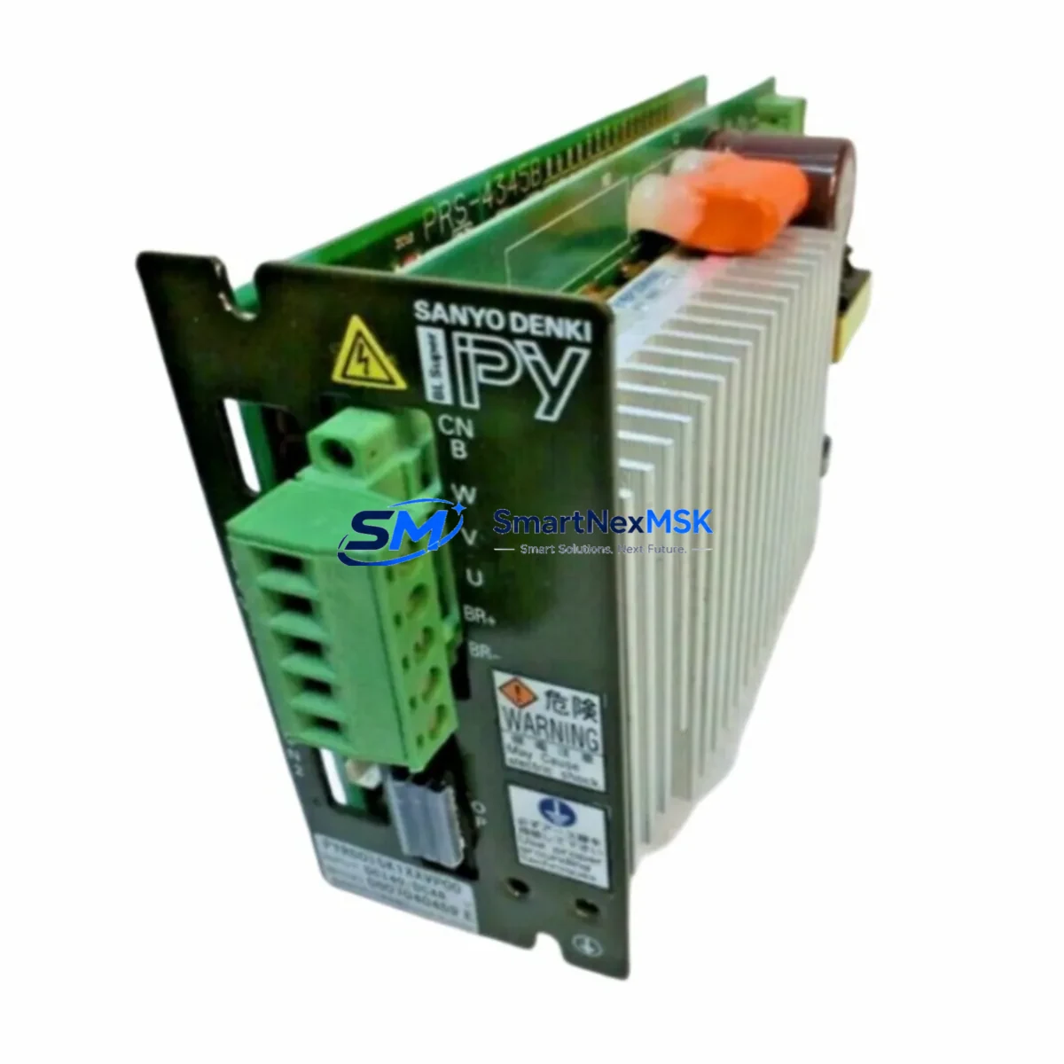
The servo amplifier paired with the QF1PA270N1 — typically from the SANYO DENKI RS2 or compatible Q Series amplifier family — should be inspected for capacitor aging, cooling fan condition, and firmware version. In many retrofit scenarios, the amplifier is replaced simultaneously with the motor to eliminate the risk of a secondary failure shortly after the motor swap. Power supply modules feeding the servo bus, including 24VDC control power supplies and main AC input contactors, should be load-tested to confirm they can support the QF1PA270N1’s rated current without voltage sag.
Terminal block assemblies connecting the motor power leads and encoder cable to the control cabinet should be inspected for corrosion, loose terminations, and insulation breakdown. Encoder cables — particularly in installations with long cable runs or high ambient vibration — are a common failure point and should be replaced proactively during a planned retrofit rather than reactively after a fault. Where the system uses a SANYO DENKI encoder battery backup unit for absolute position retention, battery condition should be verified and replaced if the installation is more than two years old.
For multi-axis systems, the rack and backplane hosting the QD75 module or motion CPU should be inspected for slot integrity and connector pin condition. I/O modules, communication modules such as QJ71C24 serial interface units, and network modules including CC-Link or MELSECNET/H cards should remain undisturbed during the motor replacement to preserve network topology and avoid re-initialization of connected field devices. Programming cables used for parameter upload and download — such as USB-SC09-A or SC-09 RS-232 adapters — should be prepared in advance to allow rapid parameter restoration after the replacement motor is installed.
Downtime Control During System Migration
Minimizing production downtime during a servo motor replacement requires a structured pre-shutdown checklist. Before de-energizing the axis, the current servo amplifier parameters should be uploaded and saved to a laptop or programming device. The PLC program — including motion subroutines, interlock logic, and home position sequences — should be backed up to both local storage and a network location. If the system uses an HMI with recipe or setpoint data linked to servo axis positions, those values should be exported as well.
During the physical swap, the motor shaft coupling or load connection should be disconnected before the motor is unbolted to prevent mechanical stress on the new unit during installation. Encoder connector seating should be verified with a continuity check before power is restored. After installation, the servo amplifier should be powered up in a test mode — with the machine in a safe, unloaded state — to confirm encoder signal integrity and verify that no drive fault codes are present before re-engaging the load.
Post-installation commissioning should include a low-speed jog test across the full travel range, verification of home position accuracy, and a comparison of actual torque and speed response against the pre-retrofit baseline. If the system uses a SANYO DENKI servo tuning tool or the amplifier’s auto-tuning function, a fresh tuning cycle should be performed to account for any mechanical differences between the original and replacement motor. Once the axis is confirmed operational, the HMI should be tested for correct alarm display, position readback, and operator control response before the machine is returned to production.
All replacement units supplied by SMARTNEXMSK are covered by a 12-month warranty against manufacturing defects and functional failures. Each unit undergoes pre-shipment functional testing and is shipped with full export documentation to support international customs clearance.
Retrofit Support FAQ
Q: Is the QF1PA270N1 a direct replacement for my existing Q Series servo motor?
A: In most Q Series installations, the QF1PA270N1 is a direct mechanical and electrical replacement. Shaft dimensions, mounting flange, and encoder interface conform to Q Series standards. We recommend verifying the motor frame size and encoder type against your existing wiring diagram before installation to confirm compatibility.
Q: What wiring checks are required before powering up the replacement motor?
A: Verify that the motor power lead terminations (U, V, W, PE) match the amplifier output terminals, confirm encoder cable shielding is intact and grounded at the amplifier end only, and check that the encoder connector is fully seated. A continuity check on the encoder cable prior to power-up is strongly recommended, particularly if the cable is being reused from the original installation.
Q: Will my existing PLC program and axis parameters work with the QF1PA270N1?
A: Yes, provided the axis parameters — including electronic gear ratio, in-position width, and torque limits — are correctly restored to the servo amplifier after installation. Back up all amplifier parameters before removing the original motor. If the amplifier is also being replaced, transfer parameters to the new unit before commissioning. No PLC program changes are required for a like-for-like motor replacement.
Q: What does the 12-month warranty cover, and how is it handled?
A: The 12-month warranty covers manufacturing defects and functional failures under normal operating conditions. Each unit is functionally tested prior to shipment. In the event of a warranty claim, contact sales@smartnexmsk.com with the order reference and a description of the fault. Replacement or repair will be arranged promptly to minimize your production impact.
© 2026 SMARTNEXMSK. All rights reserved.
Original Source: https://smartnexmsk.com
Contact: sales@smartnexmsk.com | +86 18259474341