SICK WS18-3D430 Retrofit-Ready Photoelectric Sensor for W18 Series Control Systems
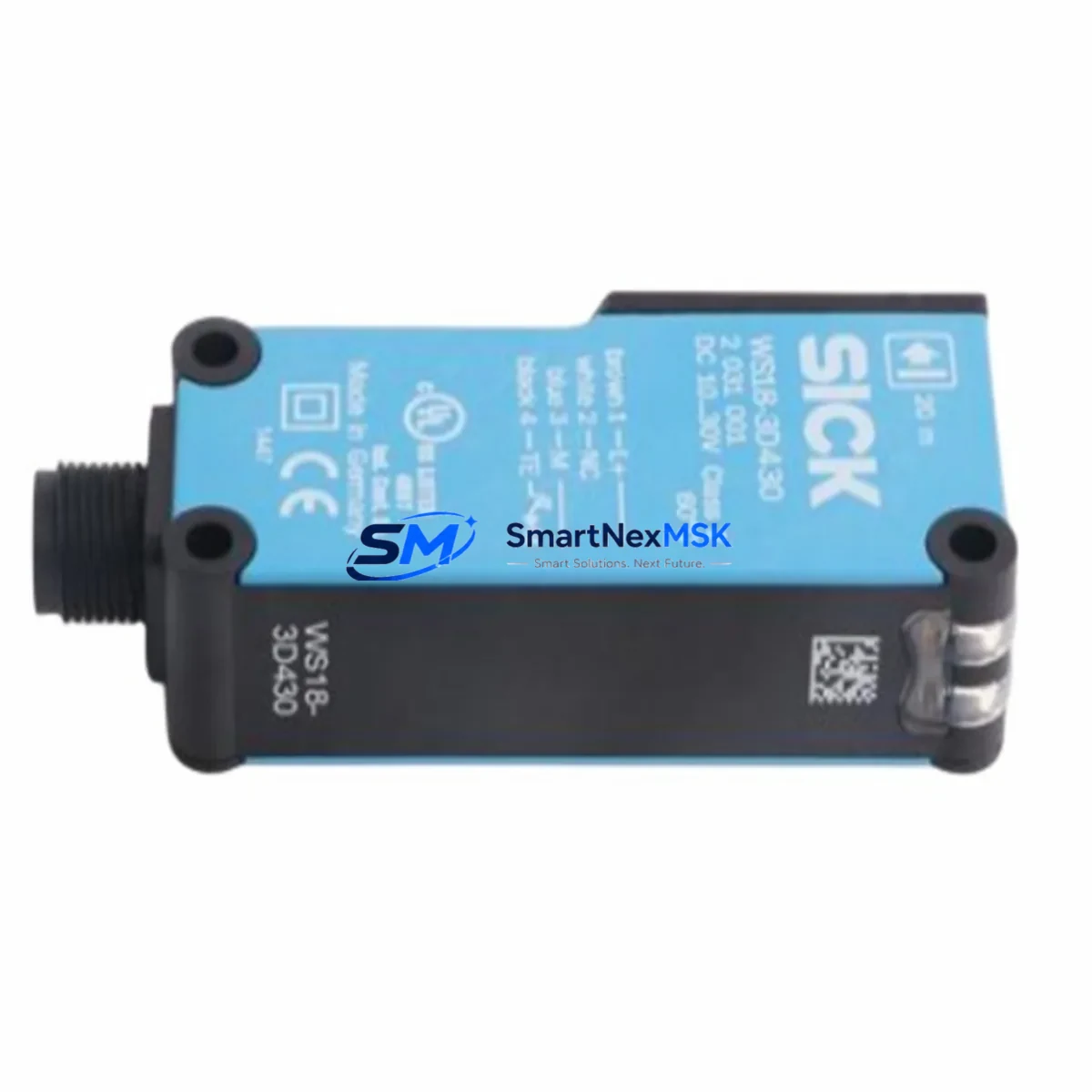
The SICK WS18-3D430 is a through-beam sender unit from SICK’s proven W18 Series photoelectric sensor family, widely deployed across automated production lines, conveyor systems, packaging machinery, and industrial control cabinets. As legacy W18 installations age and original components reach end-of-life, the WS18-3D430 serves as the primary retrofit-ready replacement for discontinued sender units in this series, enabling engineers to restore full sensing functionality without redesigning the control architecture or replacing the entire sensor pair.
This unit operates as the emitter half of a through-beam sensing system, designed to pair with compatible W18 Series receiver units such as the WE18-3D430. The WS18-3D430 maintains the same M18 threaded barrel housing, standard PNP/NPN output compatibility, and 10–30 V DC supply range that made the original W18 Series a staple in European and Asian automation installations. For retrofit projects, this means existing cable harnesses, terminal blocks, and DIN rail mounting brackets can typically be reused without modification, significantly reducing downtime during changeover.
Upgrade Compatibility Table
| Parameter | WS18-3D430 (This Unit) | Retrofit Notes |
|---|---|---|
| Housing | M18 threaded barrel | Direct fit into existing M18 mounting brackets |
| Supply Voltage | 10–30 V DC | Compatible with standard 24 V DC control cabinet supplies |
| Output Type | PNP / NPN selectable | Verify output polarity matches existing PLC input card wiring |
| Connection | M12 4-pin connector | Reuse existing M12 cordsets; verify pin assignment |
| Sensing Range | Up to 15 m (through-beam) | Align with paired WE18 receiver; no range recalibration needed for same-distance applications |
| Communication | Discrete I/O (digital) | No protocol migration required; direct wiring to digital input modules |
| Mounting | M18 x 1 thread, nut-mount | Existing lock nuts and brackets reusable |
| Warranty | 12 Months | Covered from date of shipment; includes functional verification test |
Retrofit Planning for Existing Automation Systems
When integrating the WS18-3D430 into an existing W18-based sensing circuit, the retrofit process typically begins with a power capacity audit of the control cabinet. Most W18 Series installations draw under 35 mA per sensor at 24 V DC, so the existing 24 V DC SITOP power supply or equivalent unit will generally support the replacement without derating. However, if the cabinet also houses additional I/O expansion modules, communication gateways, or recently added servo drives, it is advisable to verify the total current budget before commissioning.
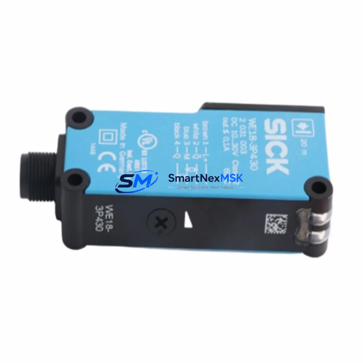
Terminal wiring for the WS18-3D430 follows the standard SICK M12 4-pin color code: brown (L+), blue (M), black (output), white (input/select). Engineers replacing a failed unit should cross-reference the original wiring diagram against the terminal strip labels in the control cabinet. In installations where the original sensor was hardwired rather than connector-mounted, a field-installable M12 connector can be crimped onto the existing cable to restore plug-and-play serviceability for future replacements.
For systems using a Siemens S7-300 or S7-400 PLC with SM 321 digital input modules, the WS18-3D430 output connects directly to the 24 V DC input channel without any intermediate signal conditioning. In newer migrations toward S7-1500 platforms with ET 200SP distributed I/O, the same wiring approach applies, though engineers should confirm the input module’s input filter time is set appropriately to avoid false triggering on fast-moving targets. If the system uses a Mitsubishi MELSEC Q Series or iQ-R Series controller with QX40 or RX40C7 input modules, the same 24 V DC discrete signal is fully compatible.
In control systems where the W18 sensor feeds into a safety relay module or a Pilz PNOZ safety controller for light curtain or presence detection applications, the replacement procedure must include a functional safety test after installation. The WS18-3D430 is a standard (non-safety-rated) sensor; if the original installation used a safety-rated variant, the replacement specification must be reviewed against the safety function requirements before commissioning.
For installations involving PROFIBUS DP or PROFINET communication backbones, the WS18-3D430 itself communicates via discrete I/O and does not require any fieldbus configuration. However, if the sensor feeds into a remote I/O station such as a Siemens ET 200M or Phoenix Contact Inline I/O block, the station address and module slot assignment should be verified in the PLC hardware configuration after the physical replacement to ensure the process image is correctly mapped.
Backplane and rack considerations are minimal for this sensor type, as the WS18-3D430 is a field-mounted device rather than a rack-mounted module. However, in control cabinet upgrades where the sensor signal is routed through a terminal block marshalling panel, engineers should inspect the terminal block condition and replace any corroded or loose terminals — particularly Phoenix Contact PTFIX or Weidmüller WDU series blocks — before finalizing the retrofit. This step is frequently overlooked but is a common source of intermittent faults after sensor replacement.
Programming compatibility is straightforward: since the WS18-3D430 provides a standard discrete output, no changes to the PLC program logic, function block parameters, or HMI screen tag assignments are required in most cases. If the original sensor’s output state is used as a trigger condition in a STEP 7 or TIA Portal program, the replacement unit will behave identically, provided the output polarity (PNP vs. NPN) matches the original configuration. HMI screens built in WinCC, FactoryTalk View, or WEINVIEW/Weintek panels that display sensor status via a discrete bit will continue to function without modification.
Downtime Control During System Migration
Minimizing production downtime during a W18 sensor replacement requires preparation before the machine is taken offline. The recommended approach is to pre-stage the WS18-3D430 unit alongside the required M12 connector, mounting hardware, and a calibrated alignment tool before the maintenance window begins. For through-beam systems, the emitter and receiver must be co-aligned on the same optical axis; having a second technician available to hold the receiver unit (WE18-3D430 or equivalent) during alignment significantly reduces the time spent on this step.
Before powering down the control system, capture a screenshot or printout of the relevant HMI diagnostic screen showing the sensor’s last known state. This provides a reference baseline for post-replacement verification. If the PLC program includes a sensor fault counter or a maintenance hour meter tag, note the current value so it can be reset or acknowledged after the replacement is complete.
During the physical swap, the M12 connector design of the WS18-3D430 allows tool-free disconnection and reconnection, reducing the mechanical intervention time to under five minutes in most installations. After reconnection, apply 24 V DC power and verify the output LED indicator on the sensor body before closing the control cabinet. A steady green LED confirms the optical path is clear and the output is in the expected state. If the LED is amber or flashing, re-check the alignment and verify that no obstruction is present in the sensing beam path.
Post-replacement, perform a full I/O force test from the PLC programming terminal to confirm the sensor signal is correctly received at the input module. Clear any pending alarms in the SCADA or DCS system, and document the replacement in the equipment maintenance log with the new unit’s serial number and installation date. All units shipped by SMARTNEXMSK are pre-tested under load conditions prior to dispatch, and each unit is covered by a 12-month warranty from the date of shipment.
Retrofit Support FAQ
Q: Is the WS18-3D430 a direct drop-in replacement for the original SICK W18 Series sender unit?
A: Yes. The WS18-3D430 uses the same M18 housing, M12 4-pin connector, and 10–30 V DC supply range as the standard W18 Series sender. In most installations, the replacement requires no wiring changes and no PLC program modifications. Verify the output type (PNP/NPN) matches your existing input module before installation.
Q: What commissioning steps are required after installing the WS18-3D430?
A: After physical installation and wiring, apply 24 V DC power and confirm the output LED status. Perform an I/O force test from the PLC to verify the signal is correctly mapped. For through-beam applications, align the emitter with the paired receiver unit and confirm the output switches correctly when the beam is interrupted. No fieldbus configuration or address assignment is required.
Q: Can the WS18-3D430 be used in systems with PROFIBUS DP or PROFINET communication?
A: The WS18-3D430 outputs a standard discrete 24 V DC signal and does not participate in fieldbus communication directly. It connects to a digital input module on the PROFIBUS or PROFINET remote I/O station. No changes to the fieldbus network configuration, GSD file, or GSDML file are required for the replacement.
Q: What does the 12-month warranty cover, and how is the unit tested before shipment?
A: Every WS18-3D430 unit shipped by SMARTNEXMSK undergoes a functional verification test under rated supply voltage and load conditions prior to dispatch. The 12-month warranty covers manufacturing defects and functional failures under normal operating conditions from the date of shipment. Warranty claims are processed via sales@smartnexmsk.com with proof of purchase and a fault description.
© 2026 SMARTNEXMSK. All rights reserved.
Original Source: https://smartnexmsk.com
Contact: sales@smartnexmsk.com | +86 18259474341