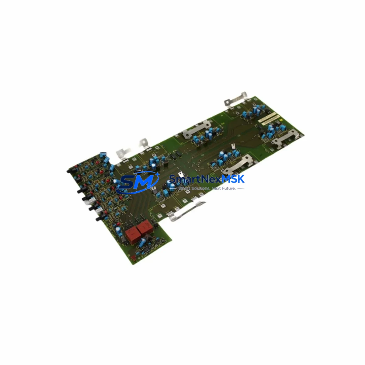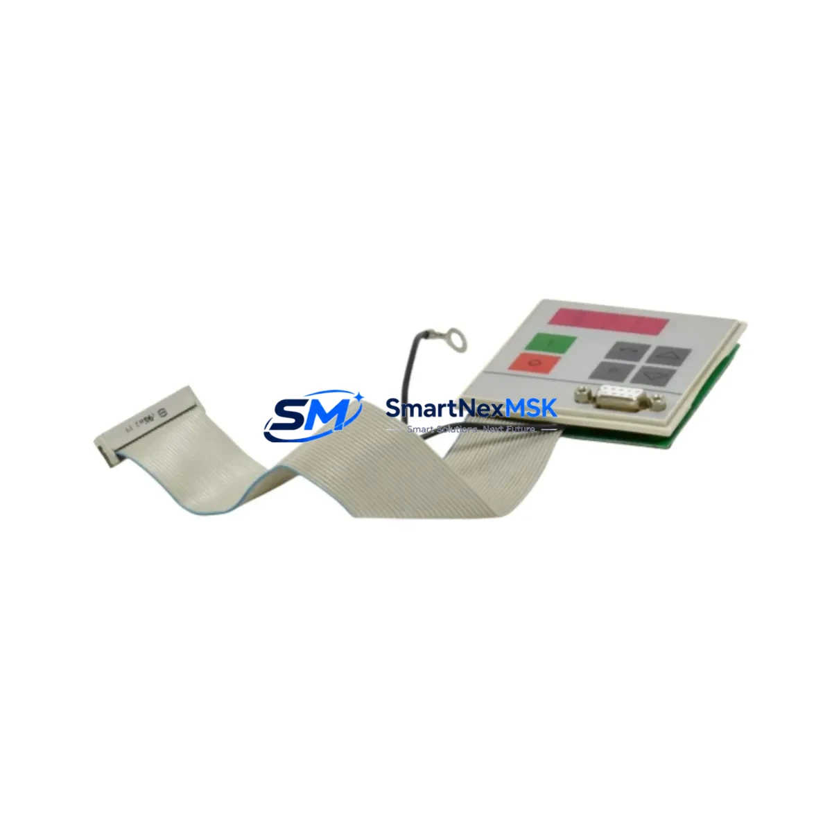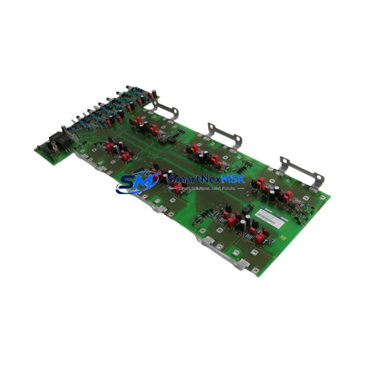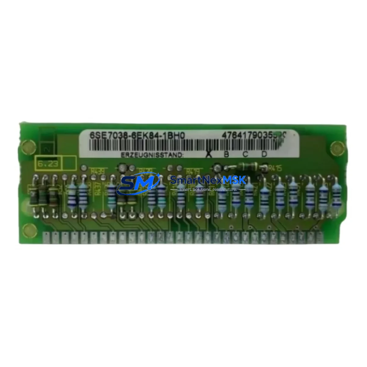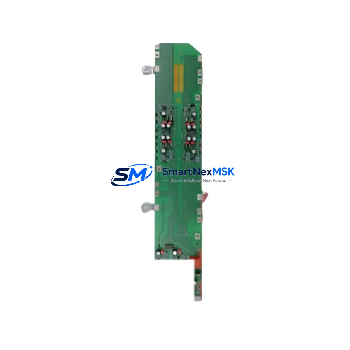
Siemens 6SE7041-4WM84-1CF0 Maintenance-Ready Spare for MASTERDRIVES MC Automation
The Siemens 6SE7041-4WM84-1CF0 is a high-power AC frequency inverter from the SIMOVERT MASTERDRIVES MC (Motion Control) series, rated at 200kW output power. Designed for demanding industrial drive applications including heavy-duty conveyors, compressors, extruders, and large pump systems, this unit delivers precise vector control performance with full PROFIBUS-DP communication capability. For maintenance engineers managing aging drive infrastructure, securing an original spare of this unit is a critical step in any downtime-prevention strategy. With lead times on large-frame drives often exceeding 12–20 weeks from OEM channels, holding a tested, ready-to-deploy 6SE7041-4WM84-1CF0 in your spare parts inventory directly reduces mean time to repair (MTTR) and protects production continuity.
Spare Maintenance Table
| Parameter | Specification |
|---|---|
| SKU / Part Number | 6SE7041-4WM84-1CF0 |
| Brand | Siemens |
| Series | SIMOVERT MASTERDRIVES MC (Motion Control) |
| Rated Output Power | 200 kW |
| Control Mode | Vector Control (VC) / Sensorless Vector |
| Communication Interface | PROFIBUS-DP (CBP2 board compatible) |
| Cooling Method | Forced air cooling |
| Protection Class | IP20 (cabinet installation) |
| Compatible Series | SIMOVERT MASTERDRIVES MC / VC |
| Origin | Germany |
| Application Environment | Industrial automation, heavy-duty drives, process control |
| Maintenance Recommendation | Inspect cooling fans, DC bus capacitors, and IGBT gate drivers annually |
| Pre-shipment Testing | Yes — powered-on functional test before dispatch |
| Warranty | 12 Months |
Maintenance Planning for Continuous Operation
When a 6SE7041-4WM84-1CF0 is flagged for replacement during a planned shutdown or emergency callout, experienced maintenance engineers know that the inverter itself is rarely the only component requiring attention. A systematic inspection of the surrounding electrical circuit and control cabinet is essential to prevent repeat failures and ensure a clean restart.
Begin with the DC bus power supply and pre-charge circuit. On large-frame MASTERDRIVES MC units, the pre-charge resistors and contactors (such as the 3RT series contactors) are subject to thermal stress and should be inspected for contact wear whenever the main inverter is pulled. Check the input line reactor — typically a 4EU or 4EP series Siemens reactor — for insulation integrity and connection tightness, as loose connections at this power level can cause nuisance trips and premature IGBT failure.
The PROFIBUS-DP communication board (CBP2) should be reseated and its termination resistor status verified. If the site uses a SIMATIC S7-400 or S7-300 PLC as the master controller, confirm that the DP address configuration matches the replacement unit’s parameter set (P918). Mismatched DP addresses are a common cause of post-replacement communication faults that delay restart.
Inspect the I/O terminal block wiring on the CU (Control Unit) board — particularly the analog speed reference inputs (X101) and digital enable signals. Terminal corrosion or loose ferrules on these low-voltage signal circuits can cause erratic speed control after the new unit is energized. If the site uses signal isolators (such as Phoenix Contact MINI MCR or Siemens SITRANS series) between the PLC analog output and the inverter reference input, verify their calibration and output range.
For sites running SIMOVERT MASTERDRIVES VC companion units in multi-drive configurations, check the DC bus coupling connections between drives. Loose or corroded bus bars at this power level represent both a safety hazard and a source of voltage imbalance that can trigger overcurrent faults on the replacement unit during initial run-up.
Do not overlook the motor thermistor (PTC) circuit connected to terminals X103. A failed or open PTC input will immediately trigger a motor overtemperature fault (F023) on startup. Verify continuity of the thermistor cable and the motor winding temperature before energizing. Similarly, inspect the encoder feedback cable if the application uses closed-loop speed control — cable shield continuity and connector pin integrity are critical for stable vector control at low speeds.
Finally, review the control cabinet ventilation filters and fan units. On 200kW-class drives, inadequate airflow is the leading cause of premature capacitor aging and IGBT thermal fatigue. Replace cabinet door filters and verify that the internal fan units (including any auxiliary 24VDC fans on the power section) are operating correctly before closing the cabinet.
Site Replacement Workflow
Step 1 — Pre-replacement documentation: Record all parameter settings from the existing unit using STARTER software or a DriveMonitor backup. The 6SE7041-4WM84-1CF0 stores application-specific parameters in its EEPROM; these must be transferred to the replacement unit before commissioning. If the original unit is non-functional, retrieve the parameter backup from your site documentation or SCADA historian.
Step 2 — Safe isolation: Follow LOTO (Lockout/Tagout) procedures. Discharge the DC bus fully before handling — on a 200kW unit, DC bus voltage can remain above 600VDC for several minutes after mains disconnection. Use a calibrated voltmeter to confirm safe levels before touching any internal connections.
Step 3 — Mechanical installation: The 6SE7041-4WM84-1CF0 is a large-frame unit requiring cabinet rail mounting. Verify that the replacement unit’s frame dimensions and mounting hole pattern match the existing installation. Torque all power terminals to the specified values (refer to the MASTERDRIVES MC installation manual, document 6SE7087-6AK85-0AA0).
Step 4 — Parameter restore and commissioning: Load the saved parameter set. Perform a motor data identification run (P115 = 2) if the motor data has not been previously optimized on this unit. Verify speed reference scaling, ramp times, and current limits before releasing to production.
Step 5 — Functional verification: Run the drive at reduced load for a minimum of 30 minutes, monitoring DC bus voltage, output current balance, heatsink temperature, and PROFIBUS communication status. Log all values before returning the system to full production load.
This structured approach minimizes restart risk, ensures compatibility, and provides a documented record for future maintenance cycles — directly supporting the goal of extending the operational life of legacy MASTERDRIVES MC installations beyond their nominal design life.
Spare Parts Support FAQ
Q1: Is the 6SE7041-4WM84-1CF0 a direct drop-in replacement for older MASTERDRIVES MC units with the same part number?
Yes, units sharing the same full part number are functionally interchangeable at the hardware level. However, firmware versions may differ between production batches. Always verify that the replacement unit’s firmware version is compatible with your site’s STARTER or DriveMonitor version before performing a parameter restore. Contact our technical team if firmware alignment is required prior to shipment.
Q2: What is your pre-shipment testing procedure for this unit?
Every 6SE7041-4WM84-1CF0 dispatched from our inventory undergoes a powered-on functional test including DC bus charge verification, control board communication check, and output phase balance measurement. A test report is available upon request. Units are packed in anti-static, shock-protected packaging suitable for international freight.
Q3: How should I manage spare parts inventory for a site running multiple MASTERDRIVES MC drives?
For sites with three or more MASTERDRIVES MC units of the same frame size, we recommend holding at least one tested spare on-site. For critical production lines, a two-unit buffer is advisable given the long OEM lead times for large-frame drives. We offer reserved stock agreements for high-volume customers to guarantee availability without requiring full upfront purchase.
Q4: What does the 12-month warranty cover, and what is the claims process?
Our 12-month warranty covers manufacturing defects and functional failures under normal operating conditions. It does not cover damage resulting from incorrect installation, overvoltage events, or operation outside the unit’s rated parameters. To initiate a warranty claim, contact [email protected] with your order number, a description of the fault, and any available fault code logs. We will arrange collection and replacement or repair within an agreed timeframe.
© 2026 SMARTNEXMSK. All rights reserved.
Original Source: https://smartnexmsk.com
Contact: [email protected] | +86 18259474341