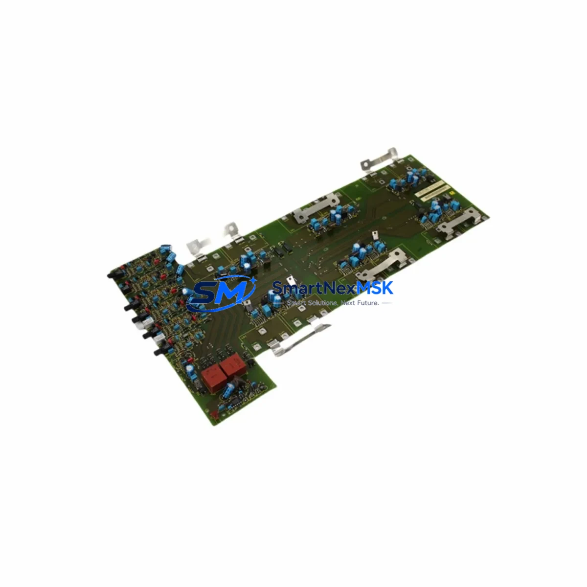
Siemens 6SE7031-7HG84-1JC1 Spare for MASTERDRIVES Automation: Spare Replacement & Industrial Downtime Risk Control
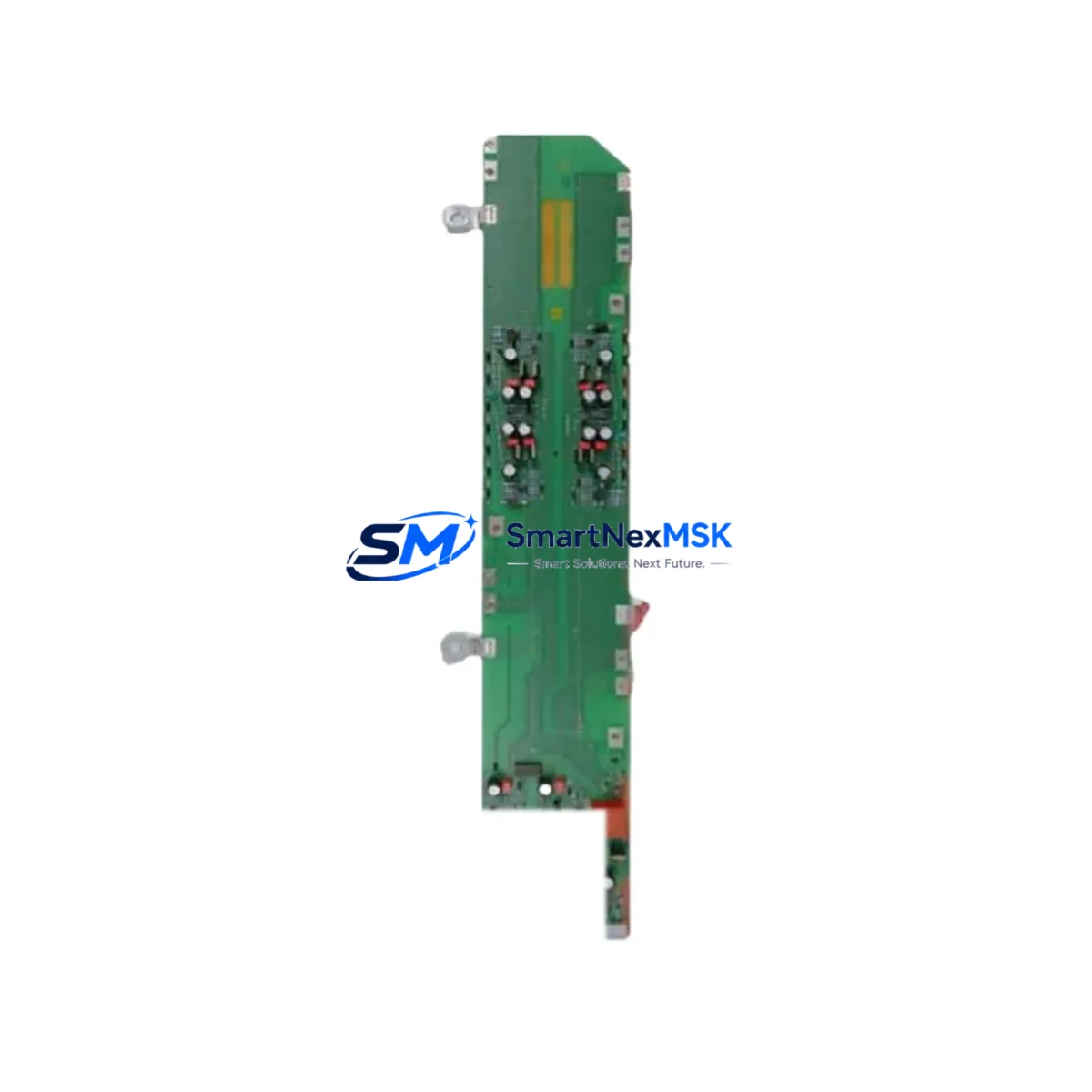
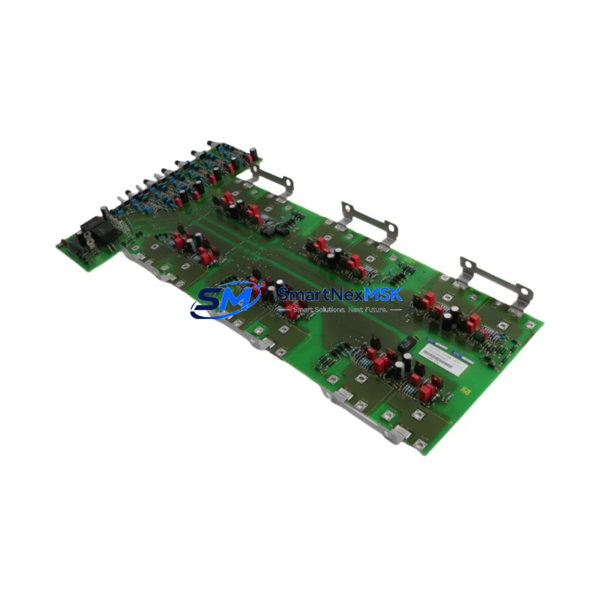
The Siemens 6SE7031-7HG84-1JC1 is an original gate driver board designed for the SIMOVERT MASTERDRIVES series of AC variable-speed drive systems. In industrial environments where continuous motor control is critical — from conveyor lines and compressor stations to pump systems and crane drives — the gate driver board is a core power electronics component responsible for IGBT switching signals. A failure in this board results in immediate drive shutdown, triggering unplanned downtime that can cascade across production cells.
Sourced as an original Siemens spare, the 6SE7031-7HG84-1JC1 is fully compatible with MASTERDRIVES MC and VC platform configurations. Each unit is inspected and function-tested prior to shipment, backed by a 12-month warranty, and supported by long-term supply continuity — making it a reliable choice for both emergency replacement and planned spare parts inventory.
Spare Maintenance Table
| Parameter | Specification / Detail |
|---|---|
| Part Number (SKU) | 6SE7031-7HG84-1JC1 |
| Brand | Siemens |
| Series | SIMOVERT MASTERDRIVES (MC / VC) |
| Component Type | Gate Driver Board (IGBT Firing Card) |
| Compatible Drive Frame | Frame Size H (high-power range) |
| Rated Power Range | Suitable for 75–160 kW drive configurations (frame-dependent) |
| Operating Voltage | DC bus interface per MASTERDRIVES power section spec |
| Signal Interface | Fiber optic / direct gate signal to IGBT modules |
| Country of Origin | Germany |
| Application Environment | Industrial automation, motor drives, process control panels |
| Compatibility | SIMOVERT MASTERDRIVES MC, VC; replaces legacy 6SE70 series gate boards |
| Installation | Direct board replacement; observe ESD precautions; re-parameterize drive after swap |
| Pre-Shipment Testing | Function-tested before dispatch |
| Warranty | 12 Months |
| Lead Time | In-stock units ship within 1–3 business days |
| Supply Continuity | Long-term availability supported for legacy MASTERDRIVES systems |
Maintenance Planning for Continuous Operation
When replacing the 6SE7031-7HG84-1JC1 gate driver board during a scheduled or emergency maintenance event, a thorough inspection of the surrounding drive system is essential to prevent repeat failures and ensure full restoration of drive performance.
Begin with the DC bus capacitor bank — capacitor degradation is a leading cause of gate driver stress and premature IGBT failure. Measure capacitance and ESR values before commissioning the replacement board. Next, inspect the IGBT power modules (such as the BSM series or equivalent Siemens-specified modules) for signs of thermal fatigue, gate oxide damage, or collector-emitter leakage — a failed IGBT can destroy a new gate driver board within seconds of power-up.
Check the 24 VDC auxiliary power supply feeding the control electronics. Voltage ripple or dropout events are a common root cause of gate driver faults in MASTERDRIVES cabinets. The 6SE7090-0XX84-0KA0 fan assembly or equivalent cooling unit should also be inspected — thermal management directly affects gate driver longevity.
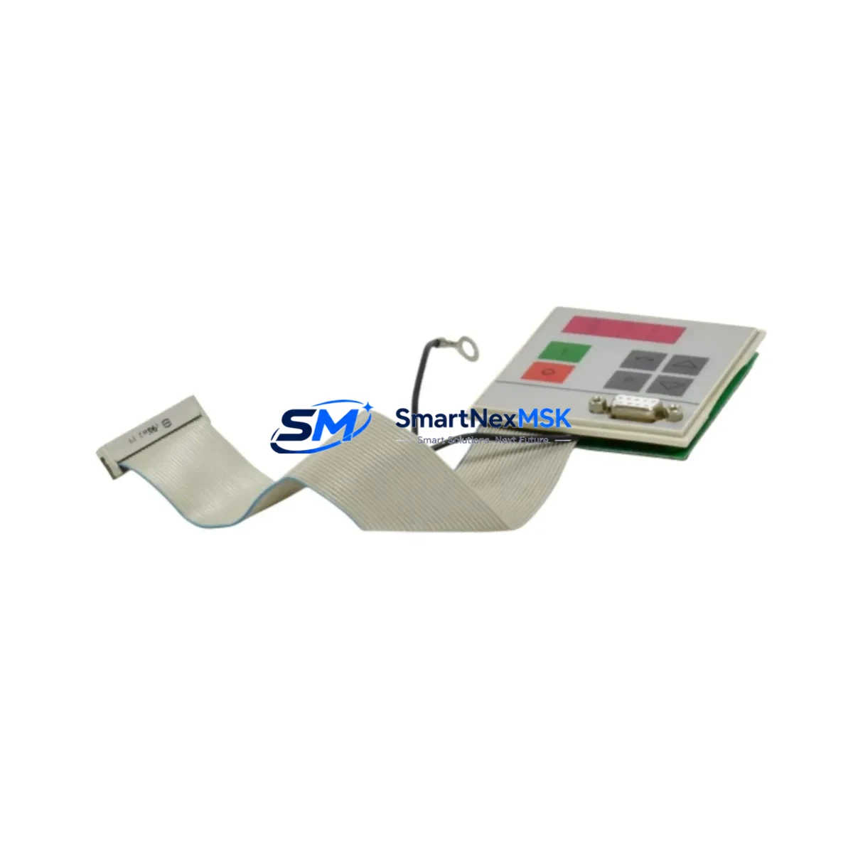
For the control side, verify the CU (Control Unit) board — such as the 6SE7031-2EF84-1JC1 or similar MASTERDRIVES CU variant — for firmware integrity and parameter consistency. Communication faults between the CU and gate driver can mimic hardware failures. If the drive uses a PROFIBUS or PROFINET communication module (e.g., CBP2 or CBC), confirm that the fieldbus interface is stable and that no telegram timeout errors are logged.
Inspect terminal blocks and control wiring on the X100/X101 connector strips for corrosion, loose crimps, or insulation breakdown — particularly in high-vibration or high-humidity environments. Review the motor feedback encoder cable and its shielding integrity; encoder signal noise can cause erratic gate firing behavior that is often misdiagnosed as a gate driver fault.
For cabinet-level inspection, check fuse holders and semiconductor fuses (e.g., 3NE-series Siemens fuses) protecting the DC bus — a blown fuse may indicate an upstream fault that must be resolved before the replacement board is energized. Finally, if the system includes a braking resistor module or chopper unit, verify its condition and connection integrity, as braking transients can impose stress on gate driver circuits.
Maintaining a structured spare parts kit — including at minimum one gate driver board, one set of DC bus fuses, and a spare CU board — significantly reduces mean time to repair (MTTR) for MASTERDRIVES-based systems.
Site Replacement Workflow
Step 1 — Isolation & Lockout: De-energize the drive, apply LOTO, and wait for DC bus voltage to discharge below 50 V (verify with a calibrated meter).
Step 2 — Documentation: Record all drive parameters using STARTER or DriveMonitor software before removing any boards. Export parameter sets to a PC or memory card.
Step 3 — Board Removal: Disconnect fiber optic cables and gate signal connectors from the existing 6SE7031-7HG84-1JC1. Note connector positions and cable routing. Use ESD wrist strap throughout.
Step 4 — Installation: Seat the replacement board firmly, reconnect all fiber optic and signal connectors, and verify mechanical alignment with the IGBT module gate pins.
Step 5 — Pre-Power Checks: Confirm DC bus fuse continuity, auxiliary supply voltage, and fan operation before energizing.
Step 6 — Commissioning: Power up the drive in a no-load condition. Verify gate pulses using the drive’s diagnostic display or STARTER. Reload saved parameters and perform a test run at reduced speed before returning to full production load.
This workflow minimizes downtime, preserves system compatibility, and ensures the replacement board is validated under controlled conditions before full-load operation resumes. For legacy MASTERDRIVES installations where original Siemens spare availability is a concern, maintaining a minimum stock of one 6SE7031-7HG84-1JC1 per drive cabinet is a recommended best practice.
Spare Parts Support FAQ
Q1: Is the 6SE7031-7HG84-1JC1 compatible with both MASTERDRIVES MC and VC variants?
Yes. The 6SE7031-7HG84-1JC1 gate driver board is designed for the SIMOVERT MASTERDRIVES platform and is compatible with both Motion Control (MC) and Vector Control (VC) configurations in the applicable frame size. Always verify the drive’s power section frame size and firmware version before installation.
Q2: How is each unit tested before shipment?
Every 6SE7031-7HG84-1JC1 unit undergoes functional inspection and electrical verification prior to dispatch. Units are checked for gate signal integrity, connector condition, and board-level continuity. A 12-month warranty is provided from the date of shipment.
Q3: Can this board replace an older or discontinued gate driver in the same MASTERDRIVES cabinet?
In most cases, yes — the 6SE7031-7HG84-1JC1 is the current or direct successor part for its frame size within the MASTERDRIVES range. Cross-reference the existing board’s part number against Siemens spare parts documentation or contact our technical team to confirm compatibility before ordering.
Q4: What is the recommended inventory strategy for critical MASTERDRIVES installations?
For production-critical drives, we recommend holding at least one gate driver board per drive cabinet as an on-site cold spare. For multi-drive systems, a shared pool of 2–3 units is typically sufficient. Pairing this with a spare CU board and a set of DC bus fuses provides comprehensive coverage for the most common MASTERDRIVES failure modes.
© 2026 SMARTNEXMSK. All rights reserved.
Original Source: https://smartnexmsk.com
Contact: [email protected] | +86 18259474341