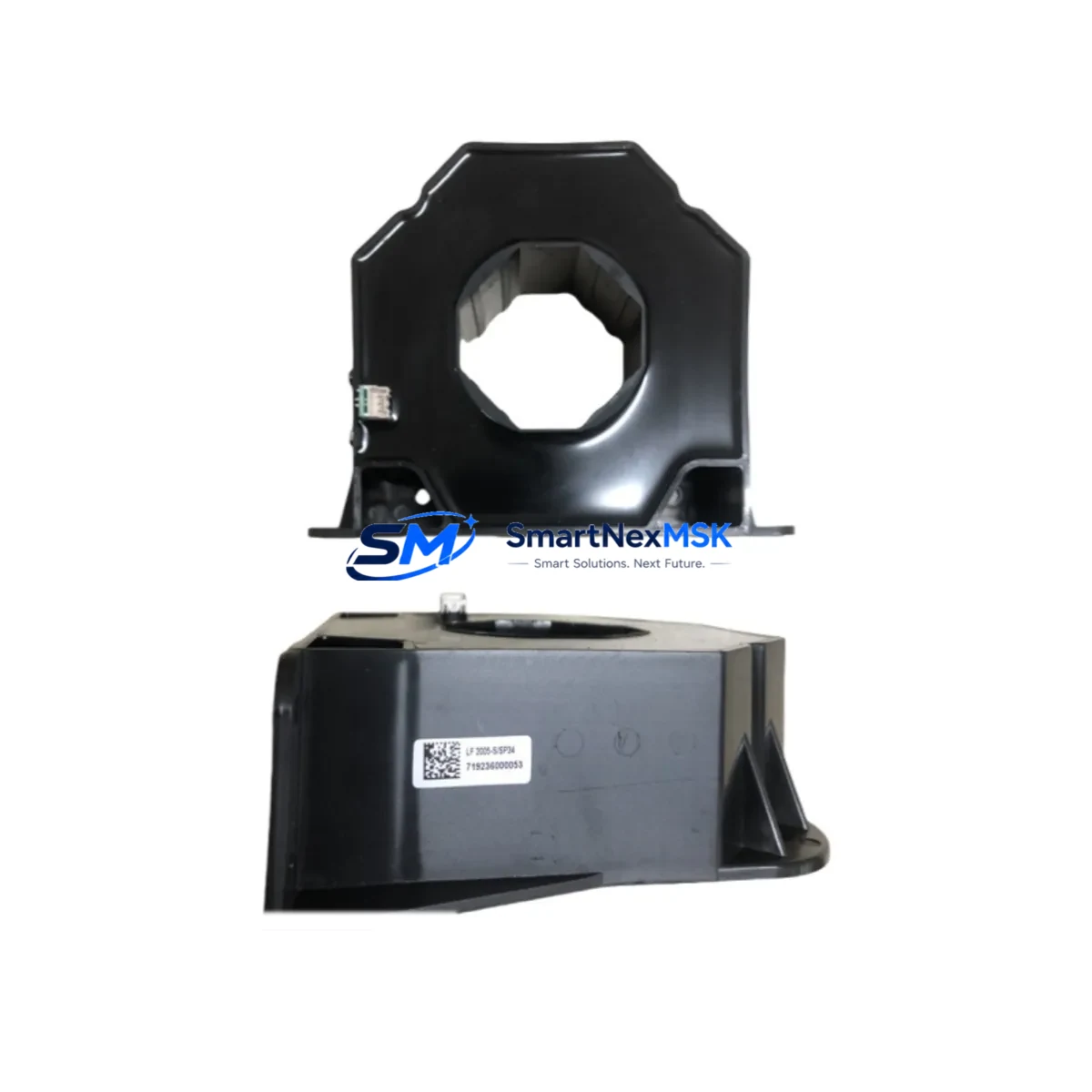
Siemens A5E31867280 Retrofit-Ready Current Transformer for SENTRON Systems
The Siemens A5E31867280 LF2005-S/SP34 is a 2000/5A current transformer engineered for seamless integration into SENTRON protection and metering systems. As legacy current transformers reach end-of-life or become unavailable through standard distribution channels, this OEM-equivalent unit provides a direct retrofit path — preserving existing wiring layouts, panel dimensions, and protection relay calibration without requiring full system redesign. For maintenance engineers managing aging switchgear or upgrading measurement circuits in industrial facilities, the A5E31867280 delivers the accuracy class and burden rating required to maintain compliant energy metering and overcurrent protection across low-voltage distribution panels.
Whether you are replacing a failed unit in a live MCC, upgrading a SENTRON PAC metering chain, or restoring measurement accuracy in a retrofitted distribution board, this current transformer ships fully tested and verified against OEM specifications. Each unit undergoes pre-shipment electrical testing to confirm ratio accuracy, insulation integrity, and terminal continuity — ensuring it is ready for immediate installation upon arrival.
Upgrade Compatibility Table
| Parameter | Specification |
|---|---|
| Part Number | A5E31867280 / LF2005-S/SP34 |
| Brand | Siemens |
| Series | SENTRON LF2005 |
| Ratio | 2000/5A |
| Accuracy Class | Class 0.5 / Class 1 (metering & protection) |
| Burden Rating | SP34 (application-specific) |
| Primary Connection | Bar-through / busbar type |
| Secondary Terminals | S1 / S2 standard screw terminals |
| Insulation Voltage | ≥ 0.72 kV |
| Mounting | Panel / DIN rail compatible |
| Replacement Compatibility | Direct retrofit for SENTRON LF2005-S series CTs |
| Communication | Analog 5A secondary output to SENTRON PAC meters |
| Commissioning Note | Verify relay burden and secondary loop resistance before energizing |
| Origin | Germany |
| Warranty | 12 Months |
Retrofit Planning for Existing Automation Systems
A successful retrofit of the A5E31867280 LF2005-S/SP34 requires a structured review of the surrounding measurement and protection circuit. Maintenance and procurement engineers should treat this replacement as an opportunity to audit the full metering chain rather than a simple component swap.
Begin by confirming the secondary burden of the connected protection relay or energy meter. SENTRON PAC3200, PAC4200, and PAC5200 power monitoring devices are common downstream loads for this CT series — each has a defined burden requirement that must be matched to the transformer’s VA rating. If the existing relay is a 7SJ or 7SR series overcurrent protection device, verify that the CT ratio and accuracy class remain within the relay’s input specification after substitution.
Inspect the secondary wiring between the CT terminals and the measuring device. Terminal blocks — particularly Phoenix Contact or Weidmüller shorting-type CT terminal blocks — should be checked for contact resistance and mechanical integrity. A degraded terminal block in the secondary circuit can introduce measurement error or, in a worst case, create an open-circuit condition on an energized CT secondary, which is a safety hazard. Replace any suspect terminal blocks as part of the retrofit scope.
For panels that include a SENTRON 3WL or 3VA circuit breaker with integrated measurement, confirm that the external CT input channel is correctly configured in the breaker’s ETU (Electronic Trip Unit) or COM15/COM16 communication module. Address settings and CT ratio parameters stored in the ETU must be updated to reflect the replacement unit if any specification differs from the original.
Where the panel feeds a SCADA or BMS system via a SENTRON 7KM PAC communication gateway or a DP/MPI-connected PAC device, verify that the analog input scaling in the PLC program — whether running on a SIMATIC S7-300, S7-400, or S7-1500 CPU — correctly maps the 5A secondary signal to the engineering unit displayed on the HMI. Incorrect scaling will produce erroneous power readings without triggering a fault alarm, making it a silent commissioning error that is difficult to detect post-startup.
Finally, review the fuse or miniature circuit breaker protecting the measurement circuit. A 2A or 4A MCB on the auxiliary supply to the PAC meter should be confirmed as functional. Replacing the CT without checking the MCB leaves a latent failure point in the circuit.
Downtime Control During System Migration
Minimizing downtime during a current transformer replacement in a live distribution panel requires preparation before the scheduled outage window. The following workflow is recommended for site engineers executing the A5E31867280 retrofit:
Pre-outage preparation: Document the existing CT secondary wiring using terminal labels and photographs. Confirm the shorting terminal block is functional and accessible — this is essential for safely isolating the secondary circuit before removing the old CT. Download and archive the current PAC meter configuration and any PLC program blocks that reference the CT input channel. Verify that the replacement unit has been received, inspected, and confirmed against the order specification.
During the outage: Short the CT secondary terminals using the dedicated shorting link before disconnecting any wiring. Remove the old transformer and install the A5E31867280 LF2005-S/SP34, ensuring correct orientation of the primary conductor relative to the polarity marking (P1 → P2 in the direction of current flow). Reconnect S1 and S2 terminals in the correct polarity. Remove the shorting link only after all secondary connections are confirmed secure.
Post-installation verification: Apply power and use a clamp meter on the primary conductor to verify that the secondary output current corresponds to the expected ratio. Compare the PAC meter reading against the clamp meter measurement. If the SENTRON PAC device shows a phase angle error or power factor anomaly, recheck S1/S2 polarity. Confirm that the SCADA or HMI display reflects the correct real-time values before releasing the panel back to service.
This structured approach consistently achieves restoration within a single planned maintenance window, avoiding repeat outages caused by commissioning errors.
Retrofit Support FAQ
Q1: Is the A5E31867280 LF2005-S/SP34 a direct replacement for older SENTRON LF2005 series current transformers?
A: Yes. The A5E31867280 is the current OEM part number for the LF2005-S/SP34 and is dimensionally and electrically compatible with earlier SENTRON LF2005 series units of the same ratio and burden class. Verify the ratio (2000/5A) and burden designation (SP34) against your existing installation record before ordering.
Q2: What commissioning checks are required after installation?
A: After installation, confirm secondary terminal polarity, remove the CT shorting link, and verify the output current ratio using a calibrated clamp meter on the primary conductor. Check the downstream PAC meter or protection relay for correct reading. Update any PLC scaling parameters if the replacement unit has a different accuracy class than the original.
Q3: How is each unit tested before shipment?
A: Every A5E31867280 unit undergoes pre-shipment testing including ratio accuracy verification, insulation resistance measurement, and terminal continuity check. A test record is available upon request. Units are packaged in anti-static, shock-protected packaging to prevent transit damage.
Q4: What warranty and long-term supply support is available?
A: Each unit carries a 12-month warranty covering manufacturing defects and electrical performance. We maintain stock inventory to support ongoing MRO and project procurement requirements. For long-term supply agreements or multi-unit project orders, contact our sales team directly.
© 2026 SMARTNEXMSK. All rights reserved.
Original Source: https://smartnexmsk.com
Contact: sales@smartnexmsk.com | +86 18259474341