Siemens FZ450R12KE3 Maintenance-Ready Spare for KE3 Series Automation
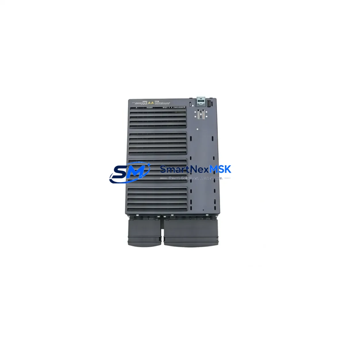
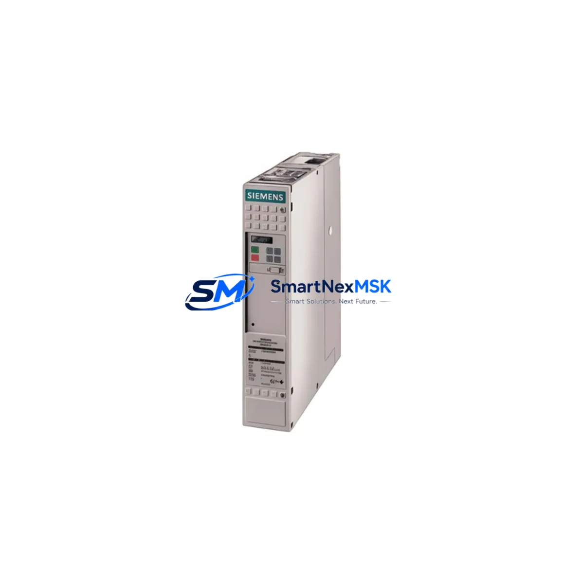
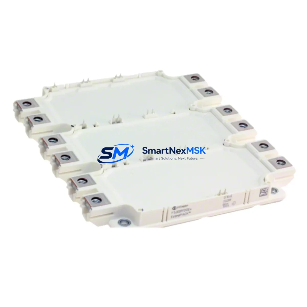
The Siemens FZ450R12KE3 is a high-performance IGBT power module rated at 1200V / 450A, belonging to Siemens’ proven KE3 series. Designed for demanding industrial environments including variable frequency drives (VFDs), traction inverters, regenerative braking systems, and medium-voltage converter stacks, this module is a critical spare component for maintenance engineers managing continuous-operation facilities. Unplanned downtime caused by IGBT module failure can halt entire production lines or traction systems within seconds. Stocking a verified replacement of the FZ450R12KE3 is a fundamental element of any proactive maintenance strategy.
Whether you are managing a scheduled overhaul, responding to an emergency fault, or conducting a routine control cabinet inspection, the FZ450R12KE3 delivers the electrical performance and dimensional compatibility required for direct replacement in Siemens drive platforms. Each unit is sourced from authorized supply chains, individually tested prior to shipment, and backed by a 12-month warranty covering manufacturing defects and electrical performance.
Spare Maintenance Table
| Parameter | Specification |
|---|---|
| Part Number / SKU | FZ450R12KE3 |
| Brand | Siemens |
| Series | KE3 |
| Module Type | IGBT Power Module (6-pack / dual) |
| Collector-Emitter Voltage (Vces) | 1200 V |
| Continuous Collector Current (Ic) | 450 A |
| Gate-Emitter Threshold Voltage | ±20 V |
| Switching Frequency | Up to 3 kHz (application-dependent) |
| Thermal Resistance (Rth j-c) | Per datasheet; heatsink compound required |
| Mounting | Baseplate with M6 screw terminals |
| Compatibility | Siemens SINAMICS, MASTERDRIVES, traction inverters; KE3-series drive stacks |
| Application Environment | Industrial drives, traction, regenerative converters, UPS systems |
| Origin | Germany (DE) |
| Condition | Original, new — tested before shipment |
| Warranty | 12 Months |
| Lead Time | In stock / ships within 3–5 business days |
Maintenance Planning for Continuous Operation
When replacing the FZ450R12KE3 in a drive or inverter stack, a thorough maintenance engineer will not stop at the IGBT module itself. The surrounding electrical circuit must be inspected and, where necessary, replaced in the same maintenance window to prevent repeat failures and ensure system reliability.
Start with the DC bus capacitor bank — electrolytic capacitors in the same drive chassis age in parallel with the IGBT module and are a common secondary failure point. Inspect the gate driver board (e.g., Siemens D156 or equivalent KE3-series driver PCB) for burnt resistors, cracked solder joints, or degraded optocouplers, as a faulty gate signal is frequently the root cause of IGBT destruction. Check the snubber capacitors and DC link fuses (fast-acting semiconductor fuses, typically 500A–700A class) for signs of thermal stress or open-circuit condition.
On the AC input side, verify the condition of the input rectifier bridge or thyristor module (e.g., Siemens SKT or equivalent) and the AC line reactor or EMC filter. These components absorb voltage transients that can otherwise propagate to the IGBT stage. Inspect all power terminal blocks and busbars for discoloration, loose torque, or arc tracking — a common finding in cabinets that have experienced a module failure event.
For the control side, verify the 24VDC SMPS power supply module feeding the control board and gate drivers. A marginal power supply with ripple or voltage sag under load can cause erratic gate signals and premature IGBT failure. If the drive communicates via PROFIBUS DP or PROFINET, inspect the communication module (e.g., CBP2 or CBC10) and its connector for corrosion or intermittent contact. Review the PLC I/O module that issues the enable and speed reference signals — a faulty analog output card can send out-of-range signals that stress the inverter stage.
Finally, check the temperature sensors (NTC/PTC) mounted on the heatsink and the cooling fan assembly. Inadequate thermal management is the leading cause of IGBT module degradation in service. Replace thermal interface material (TIM) on the module baseplate during every IGBT replacement, and verify heatsink fin cleanliness and airflow path integrity before recommissioning.
Site Replacement Workflow
Step 1 — Isolation & Lockout/Tagout: De-energize the drive, discharge the DC bus to below 50V (verify with a calibrated meter), and apply LOTO. Allow the heatsink to cool to ambient temperature before handling the module.
Step 2 — Documentation: Photograph the existing wiring, terminal assignments, and module orientation before removal. Record the drive firmware version and parameter set (upload to PLC or HMI if possible) to avoid reconfiguration errors after replacement.
Step 3 — Module Removal: Disconnect gate driver connectors and power terminals in sequence. Remove mounting screws (M6, torque to manufacturer spec). Lift the FZ450R12KE3 module vertically to avoid damaging the baseplate surface or adjacent busbars.
Step 4 — Surface Preparation & Installation: Clean the heatsink contact surface. Apply a thin, even layer of thermal compound. Position the new FZ450R12KE3, torque mounting screws to specification (typically 3–4 Nm), and reconnect power terminals and gate driver connectors per the original documentation.
Step 5 — Pre-Power Verification: Perform a diode check across all IGBT junctions with a multimeter. Verify gate driver supply voltage. Confirm DC bus fuse continuity. Only then re-energize and run a no-load commissioning test before returning the drive to production.
This workflow minimizes downtime, reduces the risk of repeat failure, and ensures the replacement FZ450R12KE3 operates within its rated parameters from the first power-on.
Spare Parts Support FAQ
Q1: Is the FZ450R12KE3 a direct drop-in replacement for older KE3-series modules?
Yes. The FZ450R12KE3 maintains dimensional and electrical compatibility with earlier KE3-series IGBT modules used in Siemens SINAMICS and MASTERDRIVES platforms. No firmware or parameter changes are required for a like-for-like replacement. Always verify the gate driver board compatibility before installation.
Q2: How is each unit tested before shipment?
Every FZ450R12KE3 unit undergoes electrical verification including junction diode forward voltage check, insulation resistance test, and visual inspection for physical damage. A test report is available upon request. Units that do not meet specification are quarantined and not shipped.
Q3: What does the 12-month warranty cover?
The warranty covers manufacturing defects and electrical performance failures under normal operating conditions for 12 months from the date of shipment. It does not cover damage resulting from incorrect installation, overvoltage events, or operation outside rated parameters. Warranty claims are processed with return authorization and inspection.
Q4: Can you support long-term or blanket orders for maintenance stock programs?
Yes. We support scheduled delivery agreements, consignment stock arrangements, and priority allocation for maintenance programs requiring guaranteed availability of the FZ450R12KE3 and related KE3-series components. Contact our technical sales team to discuss your site’s annual consumption and lead time requirements.
© 2026 SMARTNEXMSK. All rights reserved.
Original Source: https://smartnexmsk.com
Contact: sales@smartnexmsk.com | +86 18259474341