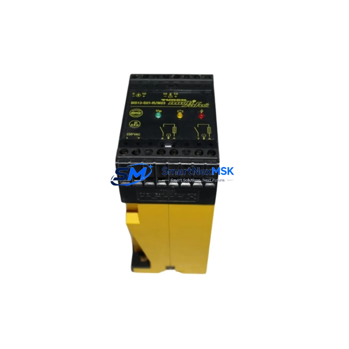
TURCK MS13-S01-R/M23 Retrofit-Ready Safety Switching Amplifier for MS Series Control Systems
The TURCK MS13-S01-R/M23 is a safety switching amplifier engineered for seamless integration into existing MS Series control architectures. As industrial facilities face increasing pressure to modernize aging safety relay circuits, discontinued safety amplifier modules, and legacy wiring panels, the MS13-S01-R/M23 provides a verified, drop-in compatible upgrade path that preserves original control logic while meeting current functional safety standards. Whether you are replacing a failed unit on a running production line or executing a planned control cabinet overhaul, this module delivers the electrical compatibility, mechanical fit, and diagnostic transparency required for confident commissioning.
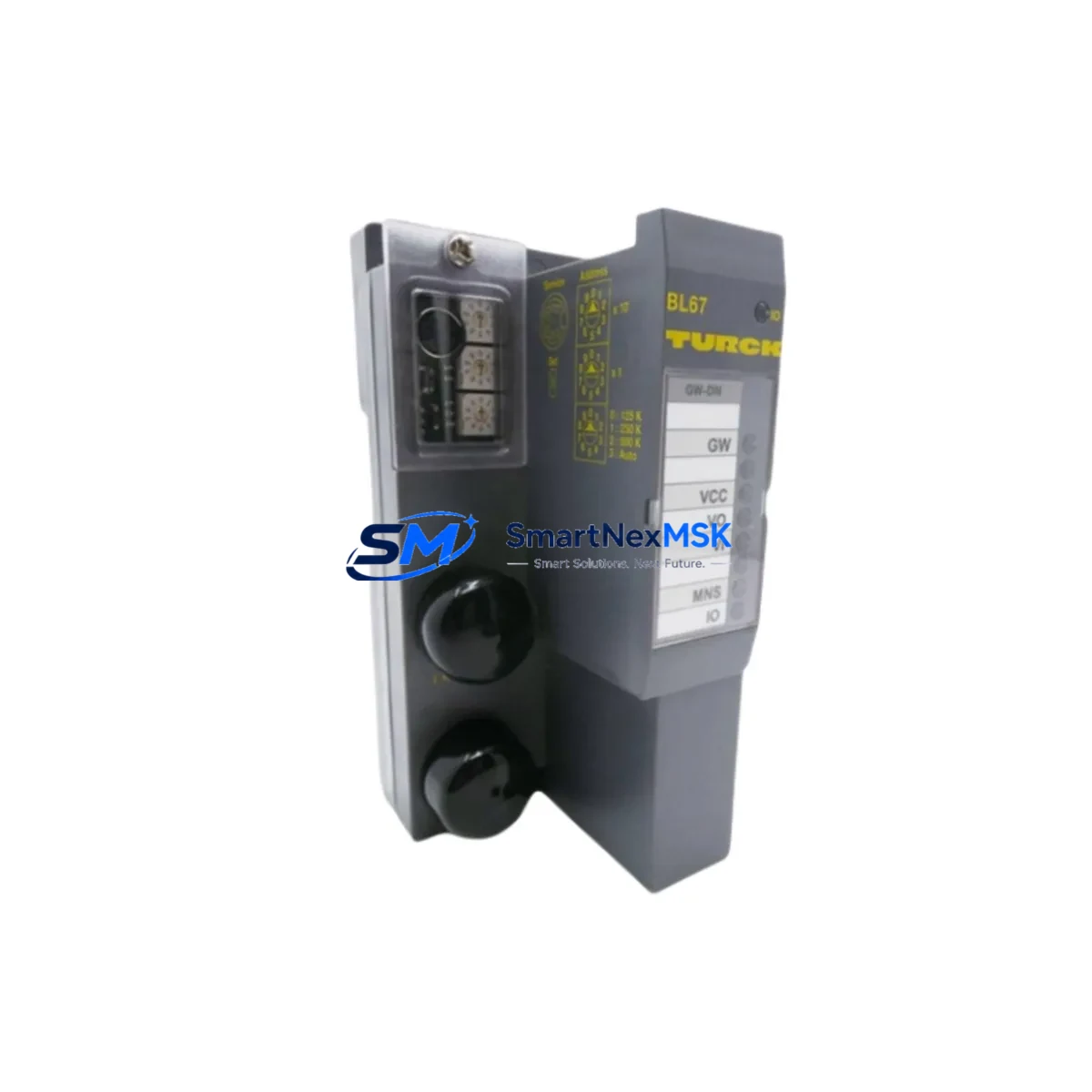
Designed around the M23 circular connector interface, the MS13-S01-R/M23 maintains pin-for-pin wiring compatibility with the original MS13 series footprint. Engineers migrating from earlier TURCK MS-series safety amplifiers — including variants such as the MS13-S01-R and related MS12 and MS14 family members — will find that terminal assignments, supply voltage range (typically 24 V DC), and output relay configurations align directly with legacy panel drawings. This eliminates the need for rewiring, reduces the risk of commissioning errors, and shortens the overall retrofit window significantly.
Upgrade Compatibility Table
| Parameter | MS13-S01-R/M23 (This Unit) | Typical Legacy Predecessor | Retrofit Notes |
|---|---|---|---|
| Connector Interface | M23 Circular Connector | M23 / Terminal Block (variant-dependent) | Verify existing cable assembly; M23 plug reuse is standard |
| Supply Voltage | 24 V DC (nominal) | 24 V DC | No power supply change required in most installations |
| Output Configuration | Safety relay output (1 NO) | Safety relay output | Confirm output channel count against original wiring diagram |
| Mounting / DIN Rail | Standard DIN rail clip | Standard DIN rail clip | Direct mechanical replacement; no bracket modification needed |
| Communication Protocol | Hardwired safety circuit | Hardwired safety circuit | No fieldbus migration required; compatible with existing E-stop loops |
| Module Address | Not applicable (hardwired) | Not applicable | No address configuration needed |
| Commissioning Requirement | Functional safety test per IEC 62061 / ISO 13849 | Same standard | Perform reset-and-test cycle; document proof-test record |
| Warranty | 12-Month Warranty — covers manufacturing defects; includes pre-shipment functional test report | ||
Retrofit Planning for Existing Automation Systems
A successful MS13-S01-R/M23 retrofit begins with a thorough review of the existing control cabinet documentation. Before removing the legacy safety amplifier, engineers should capture the current wiring diagram, photograph all terminal connections, and verify the power supply capacity of the 24 V DC rail. In many older installations, the DIN rail power supply — often a TURCK PS or equivalent 24 V regulated unit — may be operating near its rated output current. Adding a replacement module with identical or marginally different quiescent current draw is generally safe, but a current audit prevents unexpected nuisance tripping during the first power-on sequence.
The M23 connector on the MS13-S01-R/M23 mates directly with standard TURCK M23 cordsets. If the existing cable assembly is in good condition, it can be reused without modification. Inspect the cable for insulation damage, connector pin corrosion, and strain relief integrity before reconnecting. For installations where the original cordset has been spliced or field-repaired, replacement with a factory-assembled TURCK M23 cable assembly is strongly recommended to maintain the integrity of the safety circuit.
When the MS13-S01-R/M23 is installed in a system that also includes TURCK inductive safety sensors — such as the Bi series or NI series proximity switches — verify that the sensor output current and switching frequency remain within the amplifier’s specified input parameters. In multi-zone safety architectures, the amplifier may be wired in series with additional safety devices including light curtains, two-hand control modules, or door interlock switches. Each of these devices should be individually tested after the amplifier replacement to confirm that the overall safety function (SIL or PL rating) is maintained.
For control systems that incorporate a TURCK TBEN or BL20 remote I/O station alongside the safety amplifier, confirm that the safety relay output of the MS13-S01-R/M23 is correctly mapped to the corresponding I/O channel in the PLC program. If the system uses a SIEMENS S7-300 or S7-1500 safety CPU, or an Allen-Bradley GuardLogix controller, the safety program may reference a specific input tag tied to the amplifier’s feedback contact. Verify this tag assignment in the PLC project before performing the final functional test. Similarly, if an HMI panel — such as a SIEMENS TP700 Comfort or similar operator interface — displays the safety circuit status, confirm that the HMI screen tag correctly reflects the new module’s feedback signal after replacement.
In installations where the safety amplifier interfaces with a PROFIBUS DP or PROFINET network via a safety gateway, the module address and GSD/GSDML file configuration should be reviewed. Although the MS13-S01-R/M23 itself operates as a hardwired device, its output may feed into a digital input module on the network node. Ensure the input module — whether a TURCK FEN20, a Wago 750-series I/O coupler, or a Phoenix Contact Inline module — is correctly configured to read the amplifier’s relay state.
Downtime Control During System Migration
Minimizing unplanned downtime during a safety amplifier replacement requires a structured pre-work checklist and a clearly defined switchover sequence. The recommended approach is to complete all preparatory steps — documentation review, spare parts staging, tool preparation, and permit-to-work issuance — during a scheduled maintenance window rather than during an emergency breakdown response.
Before de-energizing the safety circuit, notify the production supervisor and confirm that the affected machine or line section can be safely isolated. Use the existing safety PLC’s forced-output or bypass function (where permitted by the site safety plan) to maintain downstream process continuity on non-affected zones while the amplifier is being replaced. This approach is particularly effective in multi-zone safety architectures where only one zone needs to be taken offline.
The physical replacement of the MS13-S01-R/M23 typically takes fewer than 30 minutes for a trained technician: disconnect the M23 connector, release the DIN rail clip, slide out the old module, install the new unit, reconnect the M23 cordset, and restore power. The subsequent functional test — including E-stop actuation, reset verification, and output relay confirmation — should be completed and documented before the machine is returned to production. Retaining the original PLC program without modification is the key advantage of a like-for-like replacement: no software download, no parameter re-entry, and no HMI screen reconfiguration is required.
For sites operating under a strict change-management process, the pre-shipment functional test report supplied with each MS13-S01-R/M23 unit provides the documentary evidence needed to satisfy the management-of-change (MOC) record. The 12-month warranty covers manufacturing defects and is supported by a return-material-authorization (RMA) process to minimize any secondary downtime risk.
Retrofit Support FAQ
Q1: Is the MS13-S01-R/M23 a direct replacement for the original MS13-S01-R/M23 and related MS Series variants?
Yes. The MS13-S01-R/M23 is designed as a form-fit-function replacement for the original TURCK MS13 series safety switching amplifiers. The M23 connector interface, DIN rail mounting dimensions, 24 V DC supply voltage, and safety relay output configuration are maintained. Minor firmware or diagnostic LED differences may exist between production batches; consult the current datasheet and compare with your original unit’s specifications before installation.
Q2: What wiring checks are required before connecting the replacement module?
Verify that the M23 cordset is undamaged and that all pins are clean and correctly seated. Confirm the 24 V DC supply voltage at the connector before plugging in the new module. Check that the E-stop or safety sensor wired to the amplifier input is in the de-energized (safe) state before applying power. After connection, perform a full functional test: actuate the safety input device, confirm the output relay drops, reset the amplifier, and confirm the output relay re-engages. Document the test result.
Q3: Will I need to modify the PLC program or HMI configuration after replacing the amplifier?
In a like-for-like replacement scenario, no PLC program changes are required. The safety relay output signal path remains identical. If your HMI displays a safety circuit status tag derived from the amplifier’s feedback contact, verify the tag value after the first functional test to confirm correct display. No GSDML or hardware configuration changes are needed in the PLC project for a hardwired safety amplifier replacement.
Q4: What does the 12-month warranty cover, and how is it processed?
The 12-month warranty covers manufacturing defects identified under normal operating conditions within the specified electrical and environmental ratings. Each unit ships with a pre-shipment functional test report. In the event of a warranty claim, contact our sales team to initiate an RMA. Replacement units are dispatched from stock to minimize your downtime exposure. The warranty period begins from the date of shipment.
© 2026 SMARTNEXMSK. All rights reserved.
Original Source: https://smartnexmsk.com
Contact: sales@smartnexmsk.com | +86 18259474341