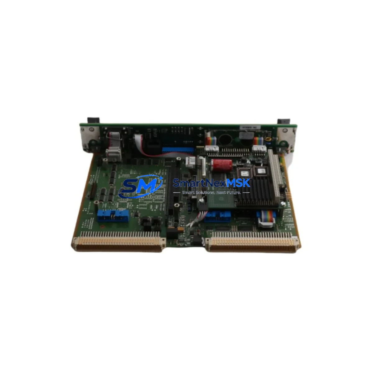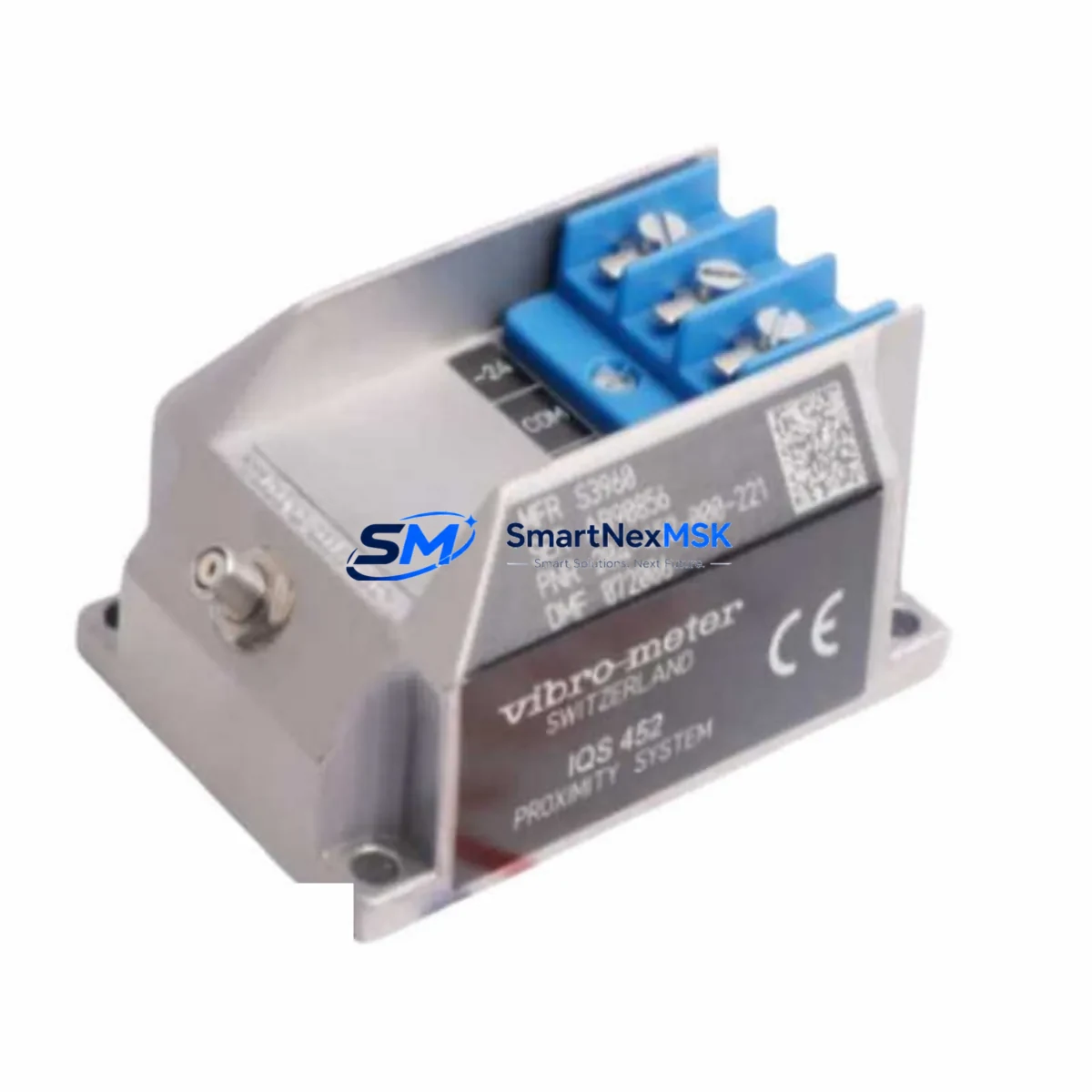
VIBRO-METER IQS452 204-452-000-221 Retrofit-Ready Eddy-Current Signal Amplifier for IQS Series Control Systems
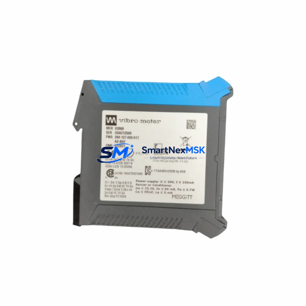
The VIBRO-METER IQS452 (Part No. 204-452-000-221) is a precision eddy-current signal amplifier engineered for demanding industrial condition-monitoring and machinery protection applications. As legacy IQS Series installations age and original spare parts become increasingly scarce, this unit serves as a verified retrofit-ready replacement that allows plant engineers to restore full system functionality without redesigning the existing measurement chain. Whether you are recovering from an unplanned failure, executing a scheduled control-cabinet upgrade, or migrating from a discontinued platform, the IQS452 is designed to slot into your existing architecture with minimal re-engineering effort.
VIBRO-METER’s IQS Series has been widely deployed in turbomachinery protection panels, compressor monitoring racks, and rotating-equipment condition-monitoring systems across power generation, oil & gas, and heavy industry. When the original IQS452 amplifier reaches end-of-life or becomes unavailable through standard distribution channels, procurement teams face pressure to source a compatible replacement quickly. Our stock of the 204-452-000-221 is maintained specifically to support these retrofit and emergency-replacement scenarios, with units dispatched after full functional verification and accompanied by a 12-month warranty.
Upgrade Compatibility Table
| Parameter | Detail |
|---|---|
| SKU / Part Number | IQS452 / 204-452-000-221 |
| Brand / Manufacturer | VIBRO-METER (Meggitt) |
| Product Type | Eddy-Current Signal Amplifier |
| Compatible Series | IQS Series (IQS452, IQS453, IQS458 platform) |
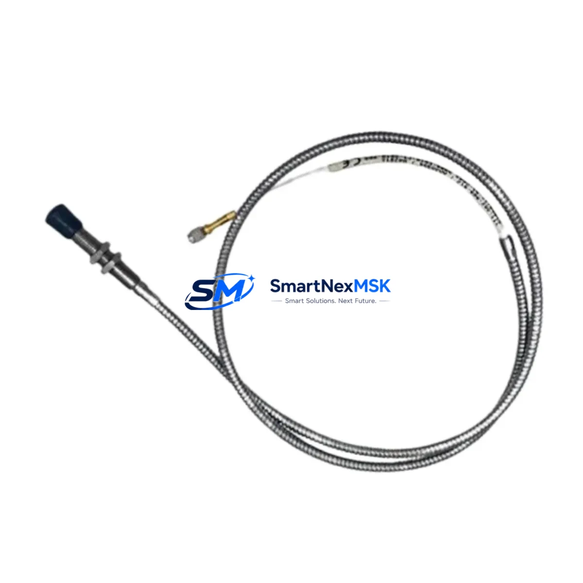
| Measurement Principle | Eddy-current (non-contact displacement / proximity) |
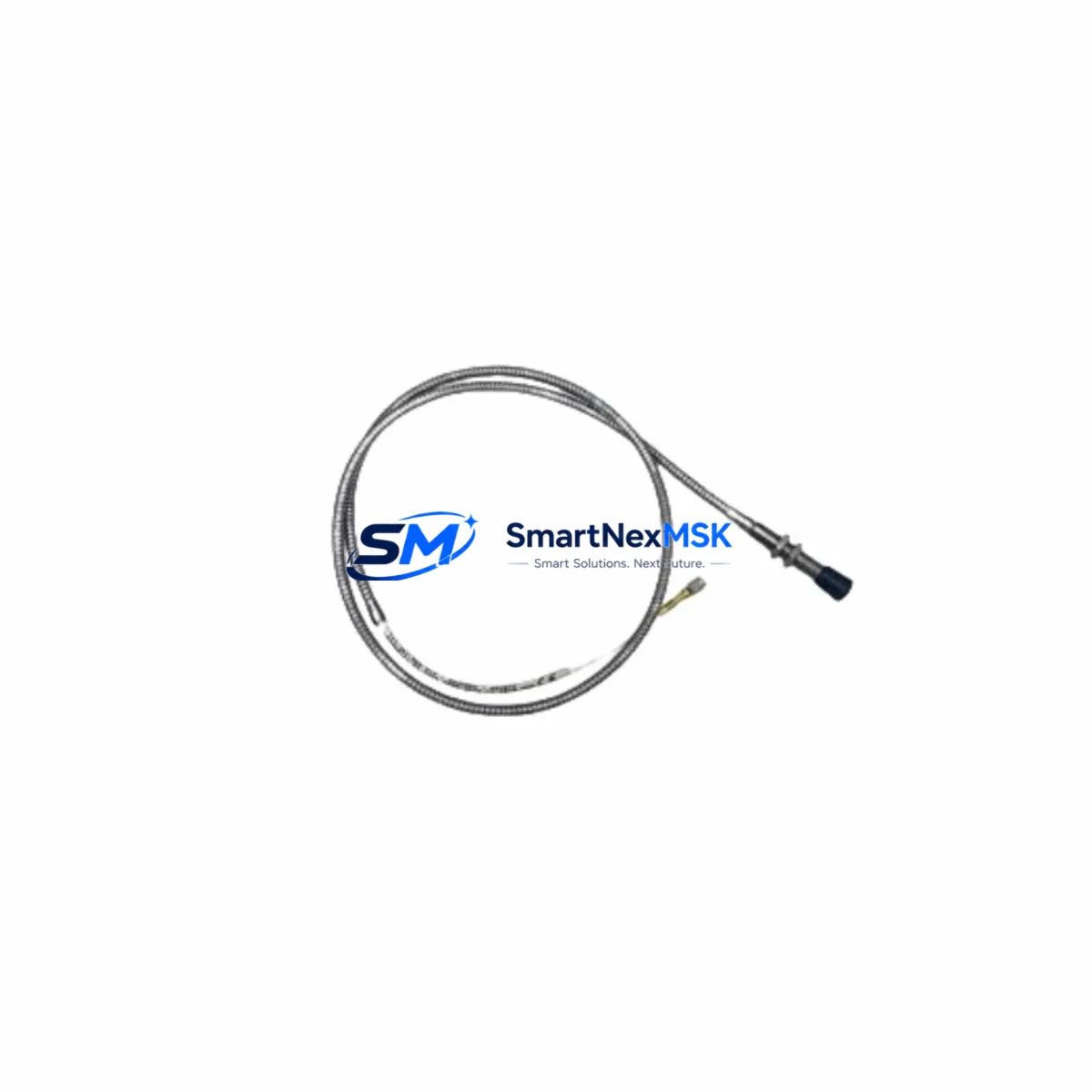
| Typical Probe Compatibility | TQ Series, QL Series eddy-current probes (8 mm / 5 mm tip) |
| Signal Output | –24 VDC proportional output (standard IQS interface) |
| Power Supply Requirement | ±15 VDC or 24 VDC (verify against existing rack PSU) |
| Mounting / Installation | DIN-rail or panel-mount per IQS Series backplane standard |
| Communication Compatibility | Analogue 4–20 mA / voltage output; integrates with VIBRO-METER CM Series and third-party DCS/PLC via standard I/O modules |
| Replacement Recommendation | Direct drop-in for 204-452-000-221; verify probe cable length and connector type before installation |
| Commissioning Focus | Gap voltage calibration, sensitivity setting, alarm threshold re-entry in monitoring system |
| Origin | Switzerland (CH) |
| Warranty | 12 months from date of shipment |
Retrofit Planning for Existing Automation Systems
A successful IQS452 retrofit begins well before the replacement unit arrives on site. Engineers should start by auditing the existing measurement chain: confirm the probe model (typically a VIBRO-METER TQ Series or QL Series eddy-current probe), measure the installed cable length, and record the current gap voltage at the nominal operating position. This baseline data is essential for re-calibrating the new amplifier to match the original sensitivity curve.
Next, inspect the rack power supply. IQS Series racks are commonly powered by a VIBRO-METER PS Series power supply module or an equivalent ±15 VDC / 24 VDC source. Confirm that the PSU has sufficient headroom to support the replacement amplifier, particularly if additional I/O cards or communication modules have been added to the rack since the original commissioning. Overloaded rack power supplies are a frequent but overlooked cause of post-retrofit instability.
Review the backplane and rack configuration. IQS Series racks use a defined slot-addressing scheme; the amplifier’s module address must match the address expected by the host monitoring system — whether that is a VIBRO-METER CM Series condition-monitoring system, a third-party Bently Nevada 3500 Series compatible interface, or a DCS I/O card such as an ABB S800 AI810 analogue input module or a Siemens ET 200SP analogue input module. Mismatched addresses will cause the monitoring system to report a channel fault even if the amplifier itself is functioning correctly.
For plants that route the IQS452 output into a PLC-based safety or control loop — for example via a Rockwell Automation 1756-IF16 ControlLogix analogue input card or a Honeywell HC900 analogue input module — verify that the 4–20 mA scaling in the PLC program still matches the new amplifier’s output range. If the original amplifier had been trimmed or had drifted over years of service, the PLC scaling may have been adjusted to compensate; restoring a factory-calibrated unit may require a corresponding correction in the PLC tag engineering-unit conversion.
HMI screens that display shaft displacement, vibration amplitude, or proximity gap values should be reviewed after replacement. Confirm that the tag names, I/O addresses, and alarm setpoints in the SCADA or DCS historian still map correctly to the physical channel. Where the plant uses a VIBRO-METER OMC Series online monitoring computer or a third-party condition-monitoring platform, re-run the channel self-test and verify that trend data resumes without gaps or offset errors.
Finally, document the as-installed configuration: probe serial number, cable length, gap voltage, sensitivity setting, and alarm thresholds. This record becomes the baseline for the next planned maintenance interval and supports future spare-parts procurement decisions.
Downtime Control During System Migration
Unplanned downtime caused by a failed eddy-current amplifier can be minimised through a structured hot-swap protocol. Where the monitoring system supports channel bypass or inhibit functions, activate the bypass on the affected channel before removing the failed IQS452. This prevents spurious trips or alarms from propagating to the safety system or DCS during the physical swap.
With the channel inhibited, remove the failed amplifier, install the replacement IQS452 (204-452-000-221), and reconnect the probe cable and power terminals. Restore power to the rack and allow the amplifier to stabilise — typically 30 to 60 seconds — before reading the gap voltage. Adjust the gap or sensitivity trimmer as required to return the output to the nominal operating point recorded during the pre-swap audit.
Once the gap voltage is confirmed, re-enter the alarm thresholds in the monitoring system, remove the channel bypass, and observe the live trend for a minimum of 15 minutes before returning the machine to full load. This sequence preserves the original program logic in the PLC or DCS, avoids the need for a full system restart, and keeps total intervention time — from channel inhibit to bypass removal — well under two hours for a prepared maintenance team.
For plants operating continuous processes where even a brief channel inhibit is unacceptable, a parallel installation approach is recommended: mount the new amplifier in an adjacent spare slot, verify its output against the live channel, then switch the monitoring system’s input assignment before removing the original unit. This approach requires a spare rack slot and is best planned during a scheduled outage window.
Retrofit Support FAQ
Q1: Is the IQS452 (204-452-000-221) a direct drop-in replacement for the original VIBRO-METER unit?
A: Yes. The 204-452-000-221 is the OEM part number for the IQS452 amplifier. Units supplied by SMARTNEXMSK are sourced from authorised channels or verified surplus stock, functionally tested prior to dispatch, and confirmed compatible with the standard IQS Series backplane and probe interface. No hardware modification is required for a like-for-like swap.
Q2: What commissioning steps are required after installation?
A: After physical installation, the primary commissioning steps are: (1) verify gap voltage at the nominal probe-to-target distance, (2) confirm output sensitivity matches the monitoring system’s expected scaling, (3) re-enter alarm and danger thresholds in the condition-monitoring or DCS system, and (4) run a channel self-test if supported by the host system. Full calibration records should be updated in the plant maintenance management system.
Q3: How do I confirm wiring compatibility before installation?
A: Compare the terminal assignment of the replacement IQS452 against the existing wiring diagram for the failed unit. Key terminals to verify are: probe input (tip, shield, body), power supply (±15 VDC or 24 VDC), signal output (–24 VDC proportional or 4–20 mA), and chassis ground. If the original wiring diagram is unavailable, the IQS Series installation manual provides the standard terminal layout.
Q4: What does the 12-month warranty cover?
A: The 12-month warranty covers manufacturing defects and functional failures under normal operating conditions from the date of shipment. Each unit is tested for output linearity, sensitivity, and power consumption before dispatch. Warranty claims are supported by SMARTNEXMSK’s technical team; contact sales@smartnexmsk.com with the order reference and a description of the fault. Return shipping and replacement dispatch are coordinated within 5 business days of claim confirmation.
© 2026 SMARTNEXMSK. All rights reserved.
Original Source: https://smartnexmsk.com
Contact: sales@smartnexmsk.com | +86 18259474341