VIPA 314-6CF02 Retrofit-Ready CPU for 300S Control Systems: Seamless Legacy Upgrade & Compatible Modernization
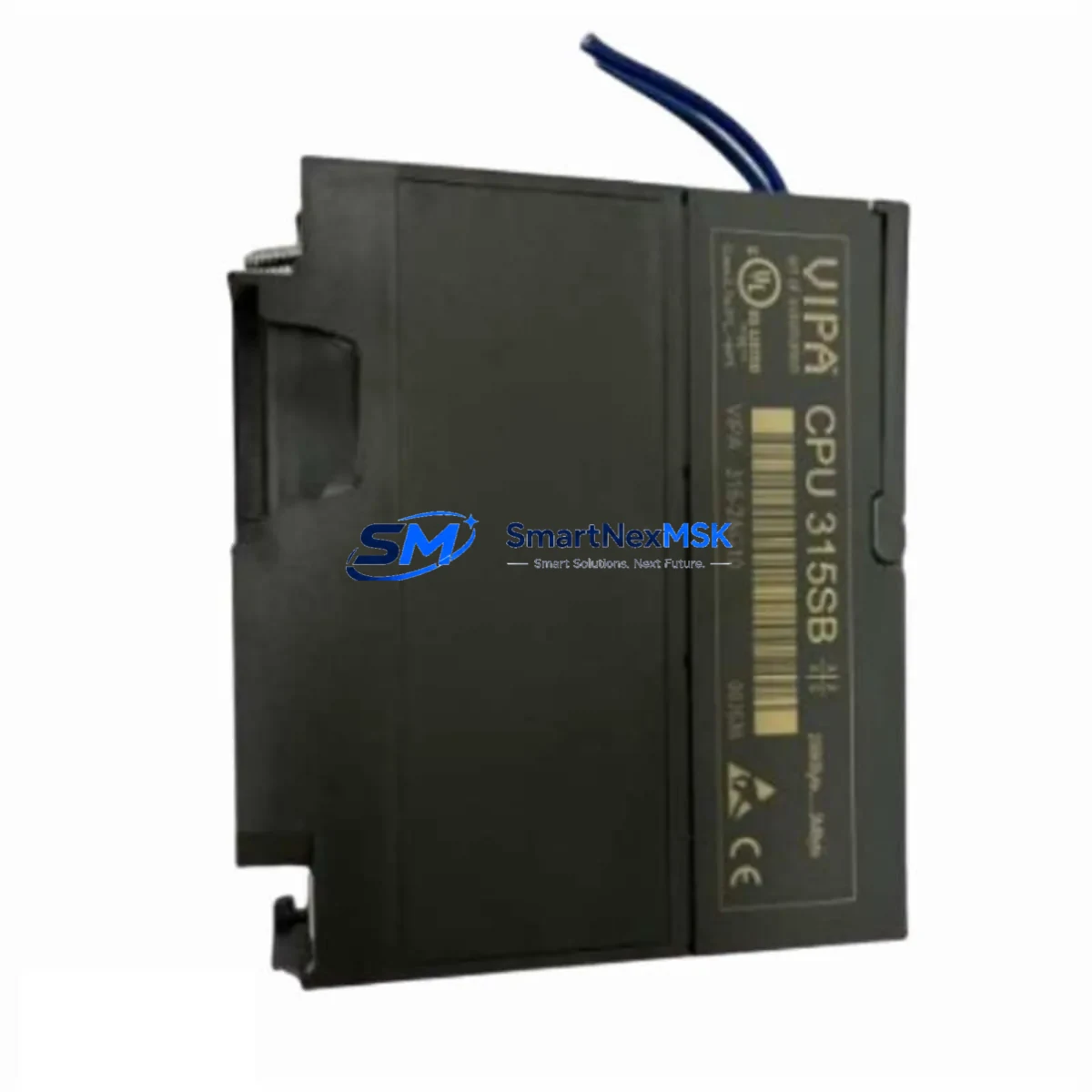
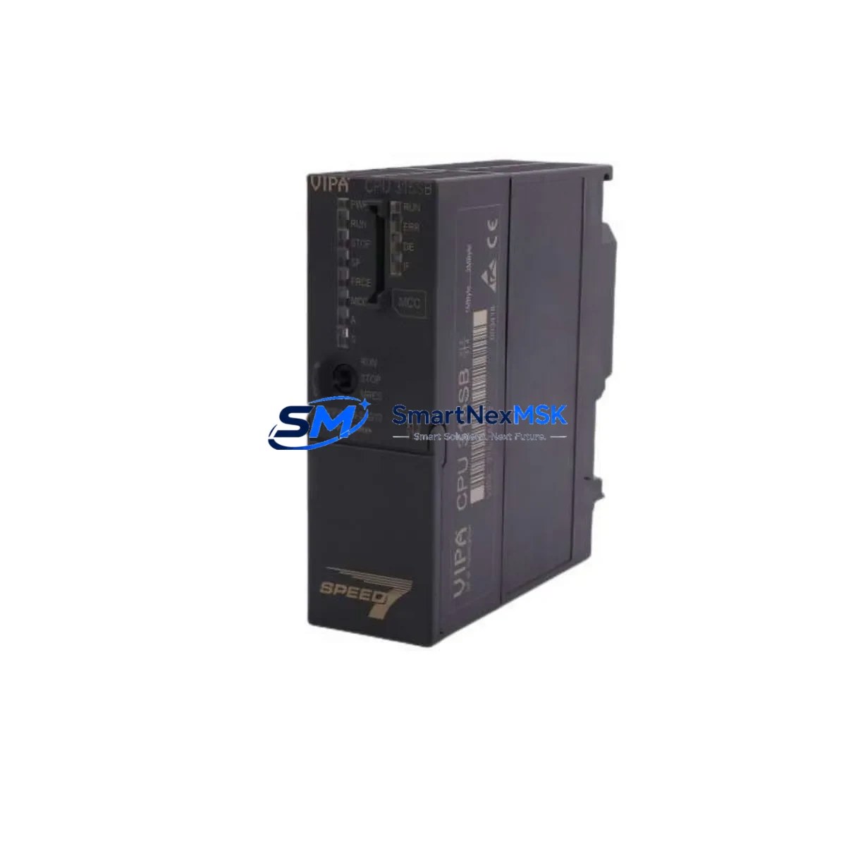
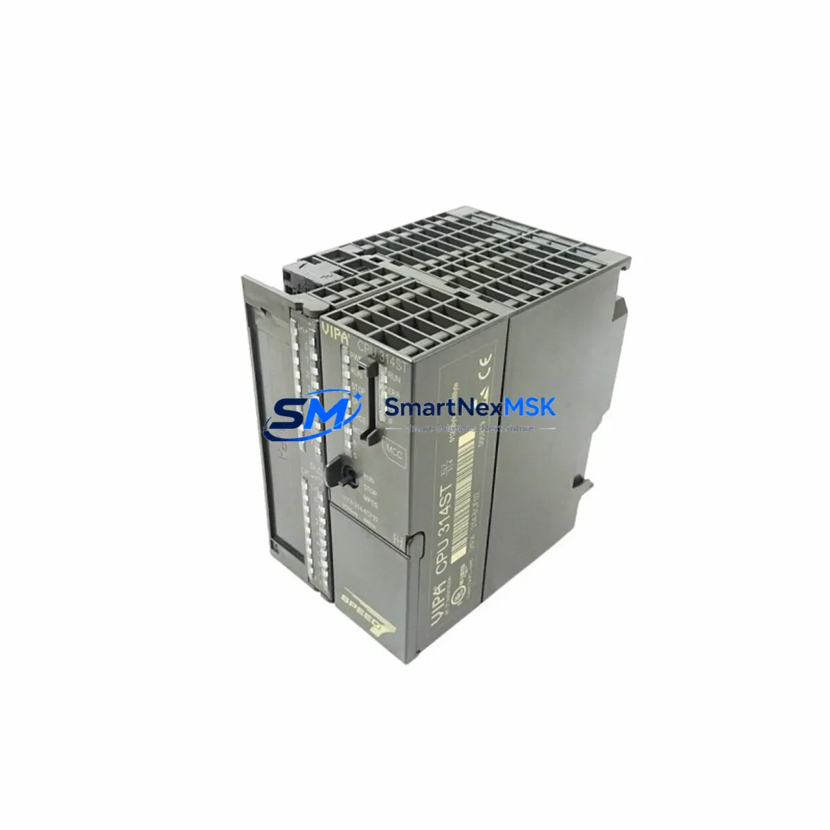
The VIPA 314-6CF02 is a high-performance CPU module engineered for the VIPA 300S Series control platform, purpose-built to serve as a direct retrofit replacement for aging Siemens S7-300 CPU 314 installations. As industrial facilities face increasing pressure to modernize legacy automation infrastructure without full system overhauls, the 314-6CF02 delivers a cost-effective, technically validated migration path that preserves existing program logic, field wiring, and HMI configurations while unlocking expanded memory capacity, enhanced communication flexibility, and improved diagnostic capability.
Whether you are managing a planned control cabinet upgrade, responding to an end-of-life parts shortage, or executing an emergency replacement for a failed CPU in a running production line, the VIPA 314-6CF02 is stocked, tested, and ready to ship with a 12-month warranty.
Upgrade Compatibility Table
| Parameter | VIPA 314-6CF02 (Replacement) | Siemens CPU 314 (Legacy) | Retrofit Notes |
|---|---|---|---|
| Form Factor | S7-300 compatible rail mount | S7-300 rail mount | Direct mechanical fit; no rail modification required |
| Communication Interfaces | MPI + Profibus DP (integrated) | MPI (standard); DP via CP module | Eliminates need for separate CP 342-5 in many configurations |
| Work Memory | Expanded (VIPA SPEED7 core) | Standard S7-300 allocation | Verify program block sizes; larger OB/FB/DB capacity available |
| Backplane Interface | Standard S7-300 bus connector | Standard S7-300 bus connector | Compatible with existing IM 360/361 expansion racks |
| Programming Software | STEP 7 v5.x / TIA Portal (via compatibility layer) | STEP 7 v5.x | Existing AWL/FBD/LAD programs upload without rewrite in most cases |
| Power Supply Compatibility | 24 VDC via PS 307 / PS 305 | 24 VDC via PS 307 | Confirm PS output current capacity ≥ 2A for CPU + I/O load |
| Module Address Assignment | Slot-based, configurable in HW Config | Slot-based | Re-configure hardware in STEP 7 HW Config after swap |
| HMI Compatibility | MPI/Profibus DP — compatible with TP/OP panels | MPI — TP/OP panels | Existing HMI screen tags and variable addresses remain valid |
| Warranty | 12 Months | OEM warranty (expired on legacy units) | Full functional test report included on request |
Retrofit Planning for Existing Automation Systems
A successful retrofit of the VIPA 314-6CF02 into an existing 300S or S7-300 control system requires systematic pre-migration planning across hardware, software, and field communication layers. The following workflow reflects best practices for industrial control system modernization projects where minimizing downtime and protecting existing program assets are the primary constraints.
Power Supply Verification: Before installing the 314-6CF02, confirm that the existing VIPA PS 307-2A or equivalent 24 VDC power supply module can sustain the combined current draw of the CPU, all installed signal modules, and any active communication modules. In expanded rack configurations using an IM 360 interface module and a secondary rack populated with SM 321 digital input modules or SM 322 digital output modules, the total bus current budget must be recalculated. Undersized power supplies are a leading cause of intermittent CPU faults during post-retrofit commissioning.
Backplane and Rack Compatibility: The 314-6CF02 installs directly onto the standard S7-300 DIN rail using the existing bus connector. In multi-rack systems, the IM 361 receive interface module in the expansion rack requires no modification. If the legacy system includes a CP 342-5 Profibus DP communication processor, evaluate whether it can be decommissioned after migration, since the 314-6CF02 integrates a native Profibus DP master/slave port — reducing rack slot consumption and simplifying the communication architecture.
Program Upload and Compatibility Check: Prior to physical module swap, perform a full program backup from the legacy CPU using a PC Adapter USB or MPI programming cable. Upload all OBs, FBs, FCs, DBs, and the system data block (SDB) to STEP 7. Review the hardware configuration for any CPU-specific parameters — particularly MPI address, Profibus DP network address, watchdog settings, and startup behavior — and replicate these in the new hardware configuration for the 314-6CF02. In most cases, existing ladder logic, function block diagrams, and structured text programs transfer without modification.
HMI Screen and Variable Mapping: If the control cabinet includes a VIPA TP 607B touch panel or a Siemens OP 7 / TP 177B operator panel connected via MPI, verify that all HMI variable addresses (DB references, M-area addresses, I/O addresses) remain consistent after the CPU swap. The 314-6CF02 preserves the standard S7-300 memory model, so existing HMI projects typically require no screen-level modifications. However, if the HMI communicates via Profibus DP, confirm the DP station address matches the configuration in the new CPU’s hardware profile.
I/O Module Address Verification: After installing the 314-6CF02 and downloading the hardware configuration, perform a forced I/O test on all SM 331 analog input modules and SM 332 analog output modules to confirm address mapping integrity. In systems with SM 374 simulation modules used during commissioning, remove these before live field testing. Verify that all ET 200M distributed I/O stations connected via Profibus DP are recognized by the new CPU during startup diagnostics.
Communication Link Restoration: For systems integrating SCADA or DCS platforms via CP 343-1 Industrial Ethernet communication processors, confirm that the CPU’s MPI address and Profibus DP configuration do not conflict with existing network node assignments. If the legacy system used a CP 342-5 for Profibus DP master functionality, the integrated DP port on the 314-6CF02 can assume this role after appropriate reconfiguration in STEP 7 NetPro.
Downtime Control During System Migration
Minimizing production downtime during a CPU retrofit is the primary operational concern for most industrial customers. The VIPA 314-6CF02 supports a structured hot-swap preparation methodology that reduces planned outage windows to under two hours in most standard S7-300 rack configurations.
Pre-Shutdown Preparation: Complete all program backups, hardware configuration exports, and HMI project archives before scheduling the maintenance window. Prepare the replacement 314-6CF02 with the correct MPI address and Profibus DP parameters pre-loaded via STEP 7 offline configuration. Stage all required tools — including the MPI programming cable or PC Adapter USB, a laptop with STEP 7 installed, and a multimeter for power rail verification — at the control cabinet before initiating shutdown.
Controlled Shutdown Sequence: Follow the established safe-state procedure for the process: place the system in manual mode, confirm all actuators are in safe positions, and initiate a controlled CPU STOP. Do not power-cycle the rack until the CPU status LED confirms STOP mode. This protects field devices and preserves the integrity of the existing program in the CPU’s load memory for reference during commissioning.
Module Swap and Restart: Remove the legacy CPU, install the 314-6CF02 in the same slot, and reconnect the bus connector and MPI/Profibus DP cables. Power up the rack and confirm the CPU enters STOP mode without hardware fault LEDs. Download the pre-prepared hardware configuration and program from STEP 7. Perform a CPU RUN command and monitor the diagnostic buffer for the first 60 seconds to confirm all I/O modules, communication processors, and distributed I/O stations initialize correctly.
Field Verification: After successful CPU startup, conduct a structured I/O verification walk — confirming digital input status, analog signal scaling, and Profibus DP slave device communication — before returning the system to automatic mode. Document the commissioning results and retain the STEP 7 project archive and hardware configuration export as the new baseline for future maintenance reference.
All units supplied by SMARTNEXMSK are subject to pre-shipment functional testing and are covered by a 12-month warranty from the date of delivery.
Retrofit Support FAQ
Q1: Is the VIPA 314-6CF02 a direct drop-in replacement for the Siemens CPU 314 (6ES7 314-1AG14-0AB0)?
A: Yes. The 314-6CF02 is mechanically and electrically compatible with the standard S7-300 rack and bus connector system. It installs in the same CPU slot without rail modification. A hardware reconfiguration in STEP 7 HW Config is required after the swap to register the new CPU type, but existing program logic, DB structures, and I/O address assignments are preserved in the vast majority of retrofit cases.
Q2: What wiring changes are required during the retrofit?
A: In most configurations, no field wiring changes are required. The 314-6CF02 uses the same 24 VDC power input and MPI port connector as the legacy CPU. If the existing system relied on a separate CP 342-5 for Profibus DP, the integrated DP port on the 314-6CF02 can replace this function — in which case the Profibus DP cable is reconnected from the CP module to the CPU’s DP port, and the CP 342-5 can be removed to free a rack slot.
Q3: How is the 314-6CF02 tested before shipment, and what does the 12-month warranty cover?
A: Every unit undergoes a pre-shipment functional test including power-on verification, CPU RUN/STOP cycle confirmation, MPI communication check, and Profibus DP port validation. The 12-month warranty covers manufacturing defects and functional failures under normal operating conditions. A full test report is available on request. Units are shipped in anti-static packaging with protective rail covers.
Q4: Can the 314-6CF02 be programmed using TIA Portal, or is STEP 7 Classic required?
A: The 314-6CF02 is natively programmed using STEP 7 v5.x (Classic). TIA Portal access is possible via the VIPA SPEED7 Studio compatibility layer or through third-party migration tools, but STEP 7 Classic is the recommended and fully validated programming environment for this CPU. Customers migrating from STEP 7 to TIA Portal as part of a broader platform upgrade should consult VIPA’s migration documentation for block conversion guidelines.
© 2026 SMARTNEXMSK. All rights reserved.
Original Source: https://smartnexmsk.com
Contact: sales@smartnexmsk.com | +86 18259474341