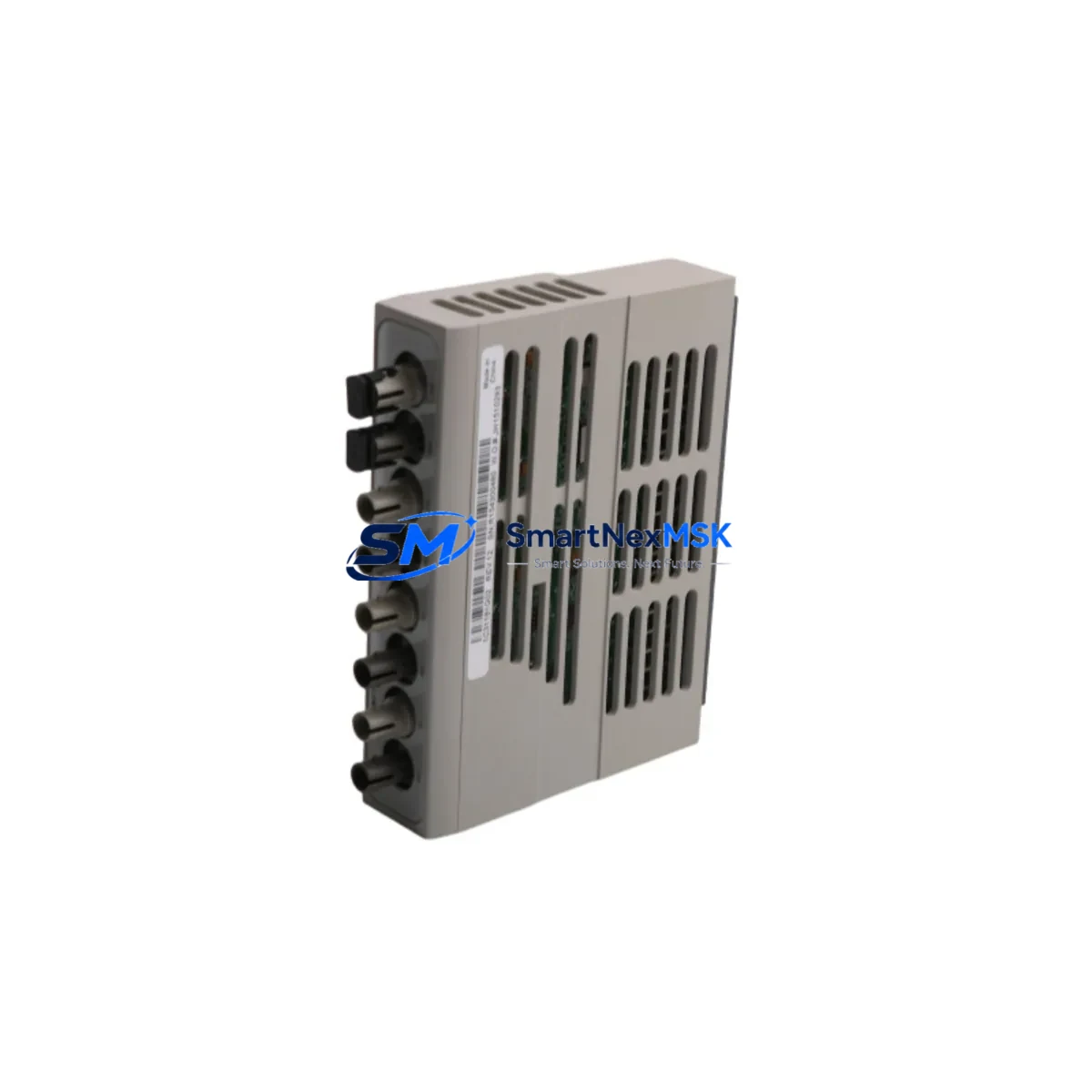
Westinghouse 5X00300G01 Retrofit-Ready Electronics Module for WDPF Control Systems
The Westinghouse 5X00300G01 is a proven electronics module designed for the WDPF (Westinghouse Distributed Processing Family) distributed control system platform. As legacy WDPF installations continue to operate across power generation, petrochemical, and process manufacturing facilities, the 5X00300G01 remains a critical spare and retrofit component for engineers managing aging control infrastructure. Whether you are replacing a failed card, upgrading a degraded control loop, or executing a phased modernization of an existing DCS cabinet, this module provides a reliable, drop-in compatible solution that minimizes engineering rework and commissioning time.
Sourced from verified industrial surplus and tested to original Westinghouse factory specifications, each 5X00300G01 unit undergoes functional verification prior to shipment. Our inventory is maintained to support urgent breakdown replacements as well as planned outage schedules, with same-day dispatch available for in-stock units. All modules are covered by a 12-month warranty against manufacturing defects and functional failure under normal operating conditions.
Upgrade Compatibility Table
| Parameter | Details |
|---|---|
| Module Part Number | 5X00300G01 |
| Compatible Platform | Westinghouse WDPF Series DCS |
| Backplane Interface | WDPF standard card cage backplane connector |
| Installation Requirement | Direct slot replacement; no hardware modification required |
| Communication Compatibility | WDPF proprietary data highway (WHnet / INFI-NET compatible nodes) |
| Replacement Recommendation | Direct replacement for failed or degraded 5X00300G01 units |
| Commissioning Notes | Verify module address configuration matches original; confirm I/O mapping in engineering workstation before energizing |
| Warranty | 12 Months — covers functional failure under normal operating conditions |
Retrofit Planning for Existing Automation Systems
Integrating the 5X00300G01 into an existing WDPF control system requires careful pre-installation planning to ensure continuity of process control. Before removing the failed module, engineers should document the current module address settings, terminal wiring assignments, and any jumper or DIP switch configurations. The WDPF card cage — typically a Westinghouse WEStation or equivalent rack assembly — uses a passive backplane that routes power and data signals to each slot. Confirming that the backplane connectors are clean and undamaged is an essential first step.
Power supply capacity is a frequent oversight during retrofit projects. The WDPF system power supply modules, such as the 1C31227G01 or equivalent redundant power units, must be verified to have sufficient headroom to support the replacement card without triggering undervoltage alarms. If the existing power supply is already operating near capacity due to previously added I/O expansion modules or communication cards, a power audit should be completed before installation.
Terminal wiring should be photographed and labeled before disconnection. WDPF field termination assemblies (FTAs) and marshalling panels use numbered terminal blocks that correspond to specific I/O channels on the module. Incorrect rewiring is one of the most common causes of post-replacement commissioning failures. Cross-referencing the original loop drawings and I/O schedule against the physical wiring is strongly recommended.
For sites that have partially migrated from WDPF to a newer platform such as Ovation DCS — Emerson’s successor architecture for former Westinghouse installations — the 5X00300G01 may be used to maintain legacy WDPF nodes that remain in service during a phased cutover. In this scenario, communication link integrity between the WDPF data highway and any Ovation gateway modules must be verified. The WDPF WHnet communication cards and associated coaxial or fiber trunk cabling should be inspected for signal degradation before the replacement module is brought online.
I/O expansion requirements should also be assessed at this stage. If the retrofit is part of a broader upgrade that adds new measurement points, additional WDPF I/O modules — such as analog input cards, digital output cards, or pulse input modules — may need to be installed in adjacent slots. Rack space availability and slot addressing must be planned in advance to avoid conflicts with existing module addresses.
HMI screen updates are often required following a module replacement if the original module was associated with specific display tags or alarm groups. Operators using the WDPF Operator Station or a connected SCADA system should verify that all process variable displays, trend groups, and alarm setpoints remain correctly mapped after the replacement is commissioned. In facilities that have transitioned HMI functions to a modern platform such as a Wonderware or FactoryTalk system, tag mapping files should be reviewed to confirm no orphaned references exist.
Programming cable access may be required if the module stores local configuration parameters. Westinghouse engineering workstations running WDPF configuration software should be used to upload and verify the module configuration after installation. Backup copies of the original configuration files should be archived before any changes are made.
Downtime Control During System Migration
Minimizing unplanned downtime is the primary operational concern when replacing a module in a live DCS environment. For the 5X00300G01, the recommended approach is to pre-configure the replacement module offline — verifying address settings, confirming firmware compatibility, and bench-testing I/O response — before scheduling the physical swap during a planned maintenance window.
Where the process permits, placing the affected control loop in manual mode at the operator station before removing the failed module prevents process upsets caused by loss of automatic control. Operators should be briefed on the expected duration of the maintenance window and prepared to manage the affected loop manually until the replacement module is confirmed online and stable.
For critical loops where even brief manual operation is unacceptable, a hot-standby or redundant module configuration should be evaluated. If the existing WDPF rack supports redundant card pairs, the replacement can be inserted into the standby slot and synchronized before the primary module is removed, achieving a bumpless transfer with no interruption to automatic control.
After the replacement module is installed and powered, a structured commissioning sequence should be followed: confirm module status LEDs, verify communication link establishment on the WDPF data highway, check I/O channel readings against field instruments, and confirm alarm and interlock logic is functioning correctly before returning the loop to automatic control. All commissioning steps should be documented in the site maintenance management system for traceability.
Retrofit Support FAQ
Q: Is the 5X00300G01 a direct drop-in replacement for the original Westinghouse module?
A: Yes. The 5X00300G01 is designed to install directly into the original WDPF card cage slot without hardware modification. Module address configuration must match the original settings, which can be verified from the existing engineering documentation or read from the failed module before removal.
Q: What commissioning steps are required after installation?
A: After physical installation, confirm the module address matches the original, verify backplane communication is established, check all I/O channel readings against field references, and confirm alarm and interlock logic is active. If the module stores local configuration, upload and verify the configuration file using the WDPF engineering workstation before returning to automatic control.
Q: How is wiring compatibility confirmed before installation?
A: Cross-reference the original loop drawings and I/O schedule against the physical terminal wiring on the field termination assembly. Photograph all wiring before disconnection. Verify terminal numbering matches the module’s I/O channel assignments as documented in the Westinghouse WDPF hardware manual for the 5X00300G01.
Q: What does the 12-month warranty cover?
A: The 12-month warranty covers functional failure of the module under normal operating conditions, including backplane communication faults, I/O channel failures, and power regulation defects attributable to the module itself. Damage caused by incorrect installation, overvoltage, or environmental factors outside the module’s rated operating range is excluded. Warranty claims are supported by our technical team with replacement or repair at no additional cost.
© 2026 SMARTNEXMSK. All rights reserved.
Original Source: https://smartnexmsk.com
Contact: sales@smartnexmsk.com | +86 18259474341