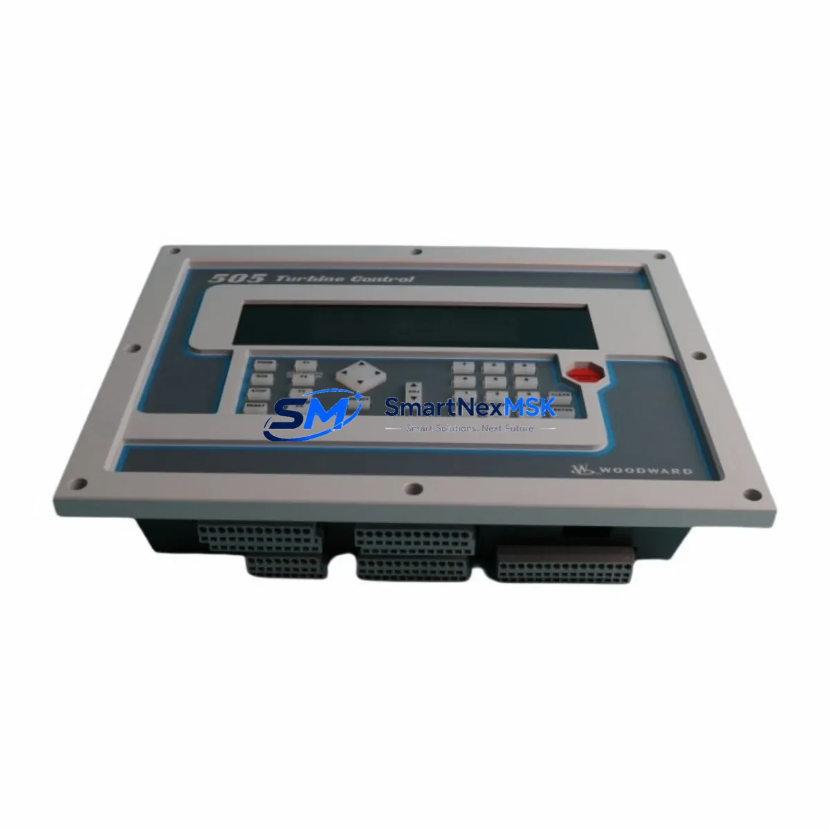
WOODWARD 5462-744 Retrofit-Ready Power Supply for MicroNet Control Systems
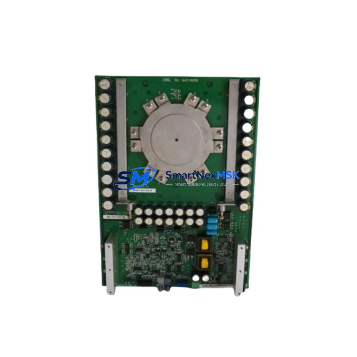
The WOODWARD 5462-744 is a proven power supply module engineered for the MicroNet distributed control platform, widely deployed across turbine control, compressor management, and industrial process automation systems. As legacy MicroNet installations age and OEM support windows close, the 5462-744 has become one of the most sought-after retrofit components for engineers tasked with extending system life, restoring failed control cabinets, or executing a phased migration to a modernized architecture — all without triggering a full system replacement.
Our inventory of the WOODWARD 5462-744 is sourced, inspected, and function-tested before shipment. Each unit is backed by a 12-month warranty covering manufacturing defects and operational failures under normal service conditions. We maintain buffer stock specifically to support emergency breakdown scenarios, planned turnaround outages, and long-lead procurement gaps that are common in the MicroNet ecosystem.
Upgrade Compatibility Table
| Parameter | Details |
|---|---|
| Compatible Platform | WOODWARD MicroNet Series (MicroNet TMR, MicroNet Plus, MicroNet Simplex) |
| Module Function | Backplane Power Supply — provides regulated DC power to MicroNet I/O and processor modules |
| Mounting / Installation | Direct backplane slot insertion; compatible with standard MicroNet rack chassis |
| Terminal Wiring | Matches original 5462-744 terminal layout; no rewiring required for direct replacement |
| Communication Compatibility | Passive power module; no protocol configuration required. Compatible with MicroNet systems using Modbus, DLAN, and proprietary WOODWARD communication links |
| Replacement Recommendation | Direct drop-in replacement for failed or end-of-life 5462-744 units; no firmware changes required |
| Commissioning Notes | Verify input voltage range, confirm backplane seating, check LED status indicators post-installation; no address configuration needed |
| Warranty | 12 months from shipment date — covers manufacturing defects and operational failures under normal service conditions |
Retrofit Planning for Existing Automation Systems
Replacing the 5462-744 in an active MicroNet control cabinet requires careful pre-work to avoid unplanned downtime and protect the integrity of the existing control logic. Before pulling the failed module, engineers should document the current power rail voltages using a calibrated multimeter and confirm that the upstream AC/DC input supply — typically a 24 VDC or 120/240 VAC feed depending on cabinet configuration — is within the module’s rated input tolerance. Verify that the MicroNet rack chassis itself, often a 5-slot or 10-slot backplane assembly, shows no signs of corrosion on the backplane connector pins, as a degraded backplane can cause repeated power supply failures even after module replacement.
In systems where the 5462-744 powers a mixed I/O rack containing analog input modules, digital output modules, and RTD input cards, it is essential to confirm that the total current draw of all installed modules does not exceed the replacement unit’s rated output capacity. MicroNet racks commonly house modules such as the 5462-740 analog input module, 5462-741 digital I/O module, and 5462-748 RTD input module alongside the power supply — each contributing to the aggregate backplane load. If the rack is near capacity, consider redistributing I/O modules across a secondary chassis before installing the replacement 5462-744.
For sites running MicroNet TMR (Triple Modular Redundant) configurations, the power supply replacement procedure must account for the redundancy voting architecture. The 5462-750 TMR processor module and its associated voter logic will flag a power channel fault during the swap window. Coordinate with the control room operator to acknowledge the fault condition and confirm that the remaining two power channels are healthy before proceeding. In simplex MicroNet installations, a brief controlled shutdown is typically required; pre-stage the replacement 5462-744 in the cabinet and minimize the swap time to reduce exposure.
Communication continuity is another critical consideration. MicroNet systems interfacing with a WOODWARD 2301D load sharing and speed control or a 505 digital governor via DLAN+ or Modbus RTU links should have their communication watchdog timers noted before the power interruption. After the 5462-744 is seated and power is restored, verify that the MicroNet operator interface panel or connected HMI screen — often a third-party SCADA or a dedicated WOODWARD display terminal — re-establishes its data link within the expected timeout window. If the HMI shows stale data or a communication fault after restart, cycle the communication module or check the RS-485 termination resistor settings on the DLAN network segment.
Sites performing a broader control system upgrade — migrating from MicroNet to a newer WOODWARD platform such as the MicroNet Diamond or integrating with a DCS via OPC-UA — should treat the 5462-744 replacement as an interim stabilization step. Maintaining a spare 5462-744 in the control room cabinet alongside a WOODWARD programming cable (P/N 1249-1001) ensures that field engineers can re-flash or verify module configuration without returning to the engineering office. Document all module slot assignments, I/O channel mappings, and alarm setpoints before beginning any migration work.
Downtime Control During System Migration
Minimizing control system downtime during a 5462-744 replacement begins with preparation, not execution. The physical swap itself typically takes under 15 minutes for an experienced field engineer; the risk lies in the pre- and post-swap phases. Before the maintenance window opens, confirm that a full backup of the MicroNet application program has been saved to a laptop running WOODWARD ToolKit software. This backup preserves all PID tuning parameters, alarm limits, sequence logic, and communication configuration — ensuring that if the replacement module triggers an unexpected fault, the system can be restored to its last known good state without re-engineering from scratch.
During the swap, use an ESD wrist strap when handling the 5462-744 to prevent electrostatic discharge damage to the backplane connector. After seating the new module, restore power in stages: energize the input supply first, observe the module’s power-good LED, then confirm that downstream I/O modules are scanning normally before releasing control to the process. In turbine or compressor applications where the MicroNet governs speed and load, do not return the unit to automatic control until all analog feedback signals — speed pickups, pressure transmitters, temperature sensors — have been verified against known-good reference values.
For planned outages, coordinate the 5462-744 replacement with other scheduled maintenance tasks in the same control cabinet to consolidate downtime. If the site also requires replacement of aging MicroNet battery backup modules or recalibration of the magnetic speed pickup interface, bundling these tasks into a single maintenance window reduces total production impact and avoids repeated shutdowns over a short period.
Retrofit Support FAQ
Q1: Is the 5462-744 a direct drop-in replacement for the original WOODWARD MicroNet power supply?
Yes. The 5462-744 is designed as a direct backplane replacement for the original MicroNet power supply module. No rewiring, address configuration, or firmware update is required. Confirm that the backplane slot and chassis model match before installation.
Q2: What pre-shipment testing is performed on each 5462-744 unit?
Each unit undergoes functional power-on testing to verify output voltage regulation, inrush current behavior, and LED status indication before shipment. Units that fail any test parameter are quarantined and not shipped. A 12-month warranty covers all shipped units against manufacturing defects and operational failures under normal service conditions.
Q3: Can the 5462-744 be used in a MicroNet TMR system without affecting the redundancy architecture?
Yes, provided the replacement procedure follows the TMR maintenance protocol: acknowledge the power channel fault in the TMR voter, confirm the remaining channels are healthy, perform the swap, and verify the replaced channel returns to the voted state before closing the maintenance window. The 5462-744 itself does not require any TMR-specific configuration.
Q4: What is the lead time and do you hold stock for emergency breakdown orders?
We maintain dedicated buffer stock of the 5462-744 for emergency breakdown scenarios. Standard orders ship within 1–3 business days. For critical breakdown situations, contact our sales team directly to confirm same-day or next-day dispatch availability based on current inventory levels.
© 2026 SMARTNEXMSK. All rights reserved.
Original Source: https://smartnexmsk.com
Contact: sales@smartnexmsk.com | +86 18259474341