Woodward 80172-110-02-3 Spare for 80172 Automation
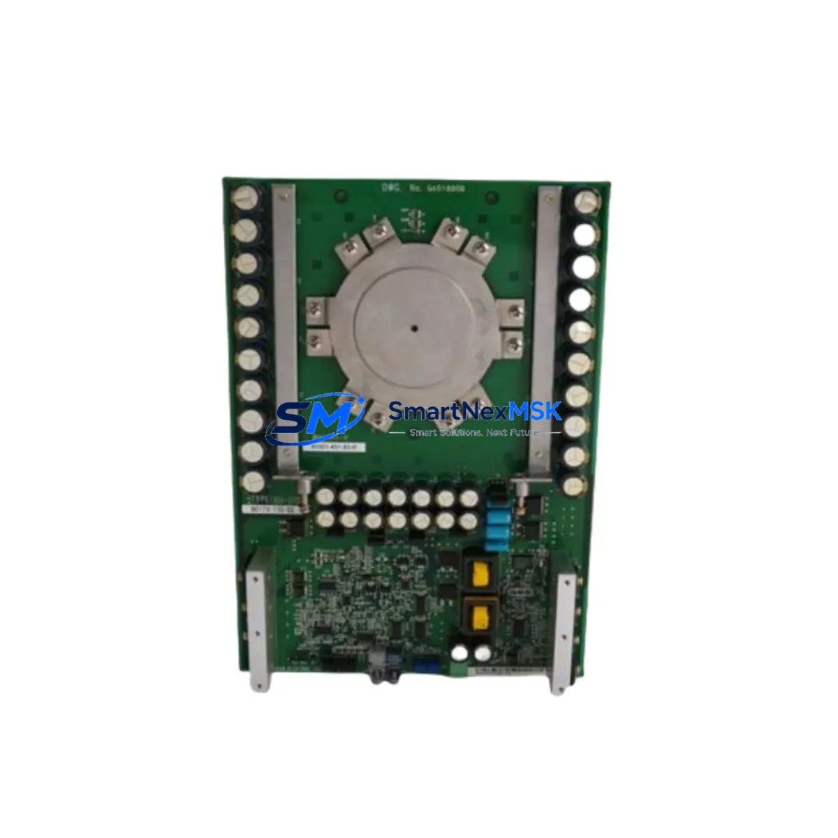
The Woodward 80172-110-02-3 is an original SCR thyristor firing board engineered for the Woodward 80172 Series governor and speed control systems. In industrial power generation, turbine control, and heavy-duty drive applications, this firing board is a critical component responsible for precise phase-angle triggering of SCR thyristor bridges. Unplanned failure of this board results in immediate loss of speed regulation, output instability, or full system shutdown — making rapid spare parts availability a core element of any maintenance strategy.
For maintenance engineers managing aging governor control cabinets, stocking a verified replacement of the 80172-110-02-3 eliminates the most common cause of extended downtime: waiting on procurement. This board ships fully tested, with electrical parameters verified against Woodward factory specifications, and is backed by a 12-month warranty covering manufacturing defects and functional performance.
Spare Maintenance Table
| Part Number | 80172-110-02-3 |
| Brand | Woodward |
| Series | 80172 Series |
| Product Type | SCR Thyristor Firing Board |
| Function | Phase-angle SCR gate triggering for governor speed control |
| Compatible Systems | Woodward 80172 Series governor control panels; turbine and generator drive cabinets |
| Input Signal | Analog speed/load reference signal from governor controller |
| Output | Isolated gate pulses to SCR thyristor bridge |
| Mounting | PCB card-cage / DIN rail compatible enclosure (per 80172 cabinet spec) |
| Operating Temperature | 0°C to +55°C (industrial panel environment) |
| Origin | USA |
| Condition | Original, new or refurbished-to-spec |
| Warranty | 12 Months — functional and manufacturing defect coverage |
| Lead Time | In-stock: ships within 1–3 business days |
| Testing | Pre-shipment functional verification included |
Maintenance Planning for Continuous Operation
When a Woodward 80172-110-02-3 firing board is flagged during routine inspection or fails in service, experienced maintenance engineers know that the fault rarely exists in isolation. A thorough cabinet inspection and system audit should accompany any board replacement to prevent repeat failures and ensure restored system stability.
Begin by checking the Woodward 80172 Series power supply module — an unstable or out-of-tolerance DC supply rail is the leading cause of premature firing board degradation. Verify input voltage levels and ripple before installing the replacement board. Next, inspect the SCR thyristor bridge assembly itself; a shorted or leaky thyristor can back-feed damaging voltage spikes into the firing board, destroying a new replacement within hours if left unaddressed.
The speed pickup sensor and signal conditioning circuit feeding the governor should be tested for signal integrity — noise or dropout on the speed reference input causes erratic firing angles and can mimic a faulty firing board. Similarly, review the analog I/O terminal blocks and wiring harness connecting the firing board to the governor controller; loose terminations and corroded contacts are common in high-vibration turbine environments.
For systems using a Woodward digital governor controller (such as the 2301A, 505, or MicroNet series), confirm that the controller’s analog output card is delivering a clean, calibrated reference signal. A miscalibrated output will prevent proper speed regulation even after a successful firing board replacement. If the cabinet includes signal isolators or galvanic isolation modules between the governor and the firing board, verify their output range and isolation integrity — degraded isolators introduce ground loops that corrupt gate timing.
Don’t overlook the fuse and overcurrent protection assembly on the SCR bridge input. Blown or weakened fuses indicate a prior overcurrent event that may have stressed the firing board. Replace fuses to rated specification and document the event in the maintenance log. Finally, if the system includes a Woodward HMI or operator panel for speed setpoint entry, confirm that the panel’s communication link to the governor is stable — a communication fault can cause the governor to default to an unsafe operating mode during restart.
Proactive spare parts inventory for the 80172 Series cabinet should include: the 80172-110-02-3 firing board, the companion power supply card, at least one set of SCR thyristors rated to the bridge specification, signal isolators, terminal block sets, and the relevant governor analog output module. This kit approach ensures that any single-point failure in the control chain can be resolved within one maintenance shift.
Site Replacement Workflow
Step 1 — Isolate and de-energize: Follow site LOTO (Lockout/Tagout) procedures. Confirm zero energy state on the SCR bridge and governor cabinet before opening the enclosure.
Step 2 — Document existing configuration: Photograph wiring, note DIP switch or jumper settings on the existing 80172-110-02-3 board, and record any trim-pot positions. These settings encode site-specific calibration and must be replicated on the replacement board.
Step 3 — Remove the faulty board: Disconnect signal connectors and gate pulse leads in sequence. Handle the PCB by edges only to avoid ESD damage to gate drive circuitry.
Step 4 — Inspect and prepare the slot: Check the card-cage connector for bent pins or corrosion. Clean with contact cleaner if required. Verify that the power supply rail voltages are within specification before inserting the replacement.
Step 5 — Install the 80172-110-02-3 replacement: Replicate all jumper and trim-pot settings from Step 2. Reconnect signal and gate leads in reverse removal order. Torque terminal screws to specification.
Step 6 — Functional verification: Energize the cabinet and perform a no-load governor response test. Confirm that SCR firing angles track the speed reference correctly across the operating range. Log results and compare against baseline commissioning data.
Step 7 — Return to service: Remove LOTO, restore system to normal operation, and update the maintenance record with the replacement date, board serial number, and test results.
This workflow minimizes downtime to a single maintenance window and ensures the replacement is fully validated before the system returns to production load.
Spare Parts Support FAQ
Q1: Is the 80172-110-02-3 a direct drop-in replacement for all 80172 Series variants?
The 80172-110-02-3 is designed for the 80172 Series firing board slot. Minor hardware revisions within the 80172 family may require jumper reconfiguration to match the specific cabinet build. Always cross-reference the cabinet wiring diagram and compare suffix codes before installation. Our technical team can assist with compatibility verification prior to shipment.
Q2: What does the 12-month warranty cover?
The warranty covers functional performance and manufacturing defects for 12 months from the date of shipment. Boards that fail to perform to Woodward specification under normal operating conditions are eligible for replacement or full refund. Damage caused by incorrect installation, overvoltage events, or failure to address upstream faults (e.g., shorted SCR thyristors) is excluded.
Q3: How is the board tested before shipment?
Each 80172-110-02-3 unit undergoes pre-shipment functional testing that verifies gate pulse output timing, signal input response, and power supply compatibility. Test records are available upon request and can be included with the shipment documentation for your maintenance file.
Q4: What is the recommended spare parts stocking strategy for long-term 80172 Series support?
For facilities operating multiple 80172 Series governor cabinets, we recommend maintaining a minimum of one 80172-110-02-3 firing board per two cabinets in active service, plus one power supply module and one set of SCR thyristors as a system-level spare kit. For single-cabinet critical applications (e.g., sole-source power generation), a dedicated hot spare is strongly advised. Long-term supply continuity is supported — contact us to discuss blanket order arrangements for multi-year inventory planning.
© 2026 SMARTNEXMSK. All rights reserved.
Original Source: https://smartnexmsk.com
Contact: sales@smartnexmsk.com | +86 18259474341