Woodward 8440-2051 Maintenance-Ready Spare for DSLC Automation
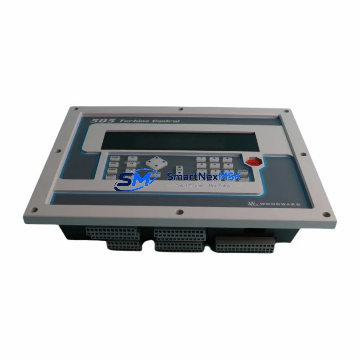
The Woodward 8440-2051 is a Digital Synchronizer and Load Control (DSLC) module engineered for precision synchronization and load sharing in industrial generator control systems. For maintenance engineers managing generator sets, switchgear panels, and parallel bus systems, this module is a mission-critical component whose failure can trigger unplanned outages across entire facilities. Stocking a verified original spare of the 8440-2051 is a fundamental element of any responsible preventive maintenance program.
Whether you are executing a scheduled overhaul, responding to a fault alarm, or managing an aging generator control cabinet, the 8440-2051 provides the synchronization accuracy and load control stability required for safe paralleling operations. This unit ships fully tested, with function verification completed prior to dispatch, and is backed by a 12-month warranty covering both parts and workmanship.
Spare Maintenance Table
| Parameter | Specification |
|---|---|
| Part Number | 8440-2051 |
| Series | DSLC (Digital Synchronizer & Load Control) |
| Brand | Woodward |
| Module Function | Generator synchronization, load sharing, kW/kVAR control |
| Supply Voltage | 18–32 VDC (nominal 24 VDC) |
| Analog Inputs | Voltage sensing, frequency sensing, load feedback |
| Communication | RS-232 / RS-485 serial interface |
| Mounting | DIN rail / panel mount, standard DSLC footprint |
| Operating Temperature | -40°C to +70°C |
| Compatibility | Direct replacement for Woodward DSLC control systems; compatible with MFR, EasyGen, and SPM series integration |
| Origin | USA |
| Condition | Original, factory-tested spare |
| Warranty | 12 Months |
| Pre-shipment Test | Function verified, load simulation tested |
| Typical Application | Diesel genset paralleling, standby power systems, industrial co-generation |
Maintenance Planning for Continuous Operation
When a Woodward 8440-2051 DSLC module is flagged for replacement during a planned inspection or emergency fault response, experienced maintenance engineers know that the module itself is rarely the only component requiring attention. A thorough site assessment should accompany any DSLC swap to prevent repeat failures and ensure the generator control system returns to full operational integrity.
Begin by inspecting the 24 VDC power supply module feeding the DSLC panel — voltage ripple or supply instability is a leading cause of premature module failure. Check the Woodward EasyGen-3000 or EasyGen-3500 generator controller if it shares the same control bus, as communication faults between the DSLC and the master controller can mask the true fault source. Verify the RS-485 communication cable and termination resistors between the DSLC and the SCADA or PLC interface, as degraded shielding introduces noise that disrupts synchronization signals.
Inspect the voltage sensing transformer (PT) and current transformer (CT) wiring connected to the DSLC analog inputs — loose terminals or corroded connections at the Phoenix Contact or Weidmüller terminal blocks are common culprits in intermittent synchronization errors. Review the Woodward SPM-D synchronizing relay or equivalent synchronizing check relay in the paralleling circuit, as a faulty relay can prevent successful bus tie even after the DSLC module is replaced.
For sites running older generator control cabinets, also evaluate the Woodward MFR 300 or MFR 500 multi-function relay for protection coordination, and confirm that the governor actuator output signal from the DSLC is reaching the engine speed control correctly. Where applicable, check the HMI panel or operator interface for firmware compatibility with the replacement DSLC module, particularly on systems that have undergone partial upgrades. Finally, inspect fuse holders and miniature circuit breakers in the DC control circuit — a blown 2A fuse on the DSLC supply line is a frequently overlooked cause of module non-response after installation.
Maintaining a coordinated spare parts inventory that includes the 8440-2051 alongside these associated components significantly reduces mean time to repair (MTTR) and supports a proactive maintenance culture aligned with ISO 55001 asset management principles.
Site Replacement Workflow
The 8440-2051 is a direct form-fit-function replacement for earlier DSLC module revisions used in Woodward generator paralleling panels. Before installation, confirm the firmware revision compatibility with your existing DSLC network configuration — in most cases, the replacement module can be configured via the Woodward DSLC PC software tool using the saved parameter file from the outgoing unit, minimizing commissioning time to under 30 minutes for experienced technicians.
Isolate the generator set from the bus before removing the faulty module. Document all terminal wiring positions and photograph the existing installation. Install the 8440-2051, restore wiring per the original schematic, and power up the control panel. Perform a dead-bus synchronization check before enabling live paralleling. Verify kW and kVAR load sharing response under partial load before returning the generator to full service. This structured workflow minimizes downtime and eliminates the risk of re-paralleling errors that can damage alternator windings or trip upstream protection relays.
For legacy systems where the original DSLC panel design is no longer supported by the OEM, the 8440-2051 spare extends the operational life of the existing control architecture without requiring a full panel redesign — a cost-effective strategy for facilities managing 10–20 year old generator infrastructure.
Spare Parts Support FAQ
Q1: Is the 8440-2051 compatible with all DSLC panel configurations?
The Woodward 8440-2051 is compatible with standard DSLC paralleling panel designs. Compatibility with specific firmware versions and communication configurations should be verified against your existing DSLC network setup. Our technical team can assist with pre-purchase compatibility confirmation based on your panel documentation.
Q2: What testing is performed before shipment?
Each 8440-2051 unit undergoes functional verification including power-up self-test, analog input response check, and communication port validation prior to dispatch. A test report is available upon request. Units are packed in anti-static, shock-protected packaging to ensure safe transit.
Q3: What does the 12-month warranty cover?
The 12-month warranty covers manufacturing defects and functional failures under normal operating conditions. It does not cover damage resulting from incorrect installation, overvoltage events, or physical mishandling. Warranty claims are processed with a target response time of 3 business days.
Q4: How quickly can the 8440-2051 be shipped for emergency downtime recovery?
In-stock units are dispatched within 1 business day. Express international shipping options are available for critical downtime situations. Contact our sales team directly for emergency order processing and lead time confirmation.
© 2026 SMARTNEXMSK. All rights reserved.
Original Source: https://smartnexmsk.com
Contact: sales@smartnexmsk.com | +86 18259474341