WOODWARD 5464-013 Maintenance-Ready Spare Turbine Automation
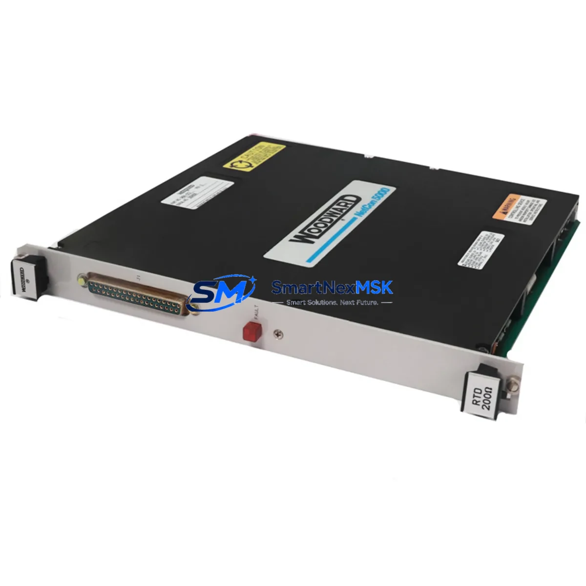
The WOODWARD 5464-013 is an original input driver module engineered for continuous-duty turbine and engine control systems. As a critical interface component within WOODWARD’s control architecture, this module handles signal conditioning and input processing for speed, temperature, and process feedback channels. When a 5464-013 fails or degrades, the entire control loop is at risk — making rapid spare availability the single most important factor in minimizing unplanned downtime. Sourced directly from authorized supply chains and tested prior to shipment, this unit ships with a 12-month warranty and is ready for immediate site installation.
Maintenance engineers managing turbine-driven compressors, generators, or pump trains understand that the 5464-013 does not operate in isolation. It sits within a broader WOODWARD control cabinet alongside power supply modules, output driver boards, communication interface cards, and the main CPU or controller card. A failure event that implicates the 5464-013 should always trigger a systematic inspection of adjacent components — not just a like-for-like swap — to prevent repeat failures and ensure the restored system meets original design intent.
For procurement engineers, maintaining a minimum of one 5464-013 in the site spare parts inventory is strongly recommended for any installation where this module is part of the active control loop. Lead times for original WOODWARD components can extend beyond acceptable downtime windows, making pre-positioned stock the only reliable strategy for emergency recovery. Our long-term supply capability ensures you can replenish stock without sourcing risk.
Spare Maintenance Table
| Parameter | Specification / Detail |
|---|---|
| Part Number / SKU | 5464-013 |
| Brand | WOODWARD |
| Module Type | Input Driver Module |
| Series / Platform | WOODWARD Turbine & Engine Control Systems |
| Application | Signal input conditioning for turbine, compressor, and engine control loops |
| Input Signal Compatibility | Analog and discrete process inputs (speed, temperature, pressure feedback) |
| Installation Environment | Industrial control cabinet; DIN rail or card rack mounting |
| Operating Temperature | 0°C to +60°C (typical industrial panel rating) |
| Origin | United States |
| Unit Weight | 920 g |
| Compatibility | Direct replacement for OEM 5464-013 installations; verify firmware revision before swap |
| Maintenance Recommendation | Inspect connector pins, signal wiring, and adjacent power rails during replacement |
| Pre-Shipment Testing | Functional test performed before dispatch |
| Warranty | 12 Months from date of shipment |
| Lead Time | In-stock units ship within 3–5 business days |
Maintenance Planning for Continuous Operation
Replacing the WOODWARD 5464-013 in a live turbine or engine control system is rarely a standalone task. A disciplined maintenance workflow requires the engineer to assess the full signal chain before returning the system to service. Begin with the upstream power supply module — WOODWARD control cabinets typically use dedicated 24 VDC or 28 VDC regulated power supply cards, and a marginal supply rail is a common root cause of input module degradation. Verify output voltage and ripple before installing the replacement 5464-013.
Next, inspect the field wiring termination blocks and terminal strips connected to the module’s input channels. Loose or corroded terminals introduce noise and intermittent faults that can damage a new module within weeks of installation. If the cabinet uses WOODWARD output driver modules on the same backplane or card rack, check those boards for signs of thermal stress or connector wear — shared backplane power distribution means a fault on one card can stress adjacent modules.
For systems using WOODWARD communication interface modules (such as Modbus RTU, CAN, or proprietary serial links), confirm that the communication bus is stable and that the replacement module’s firmware revision is compatible with the controller’s current software version. A mismatch here can cause the controller to reject the new module or log persistent diagnostic faults.
Signal isolators and signal conditioners between field sensors and the 5464-013 input channels should also be inspected. Degraded isolators can pass DC offset or noise that accelerates input module wear. Similarly, check any inline fuses or circuit protection devices on the input signal lines — a blown fuse on a sensor circuit is often the first indicator of a wiring fault that caused the original module failure.
If the system includes an HMI panel or operator workstation connected to the WOODWARD controller, use the diagnostic screens to verify that all input channels are reading correctly after the replacement module is installed and powered. Do not return the turbine or engine to automatic control until all input channels show expected values within calibrated ranges. For older WOODWARD installations approaching end-of-support lifecycle, this replacement event is also an appropriate time to audit the full spare parts list and identify other modules — CPU cards, I/O expansion boards, relay output modules, and communication cards — that should be pre-positioned in the site warehouse.
Site Replacement Workflow
Step 1 — Isolation and Lockout: Follow site LOTO procedures. De-energize the control cabinet and confirm zero-energy state on all power rails before opening the enclosure.
Step 2 — Documentation: Photograph the existing 5464-013 installation, including wiring labels, connector positions, and any DIP switch or jumper settings. Record the firmware or revision label on the outgoing module.
Step 3 — Module Removal: Disconnect field wiring connectors in sequence. Remove the module from the card rack or DIN rail mounting. Inspect the vacated slot for debris, corrosion, or damaged backplane connectors.
Step 4 — Replacement Verification: Confirm the replacement 5464-013 part number and revision match the outgoing unit. Check that any configurable settings (jumpers, DIP switches) are set identically to the original.
Step 5 — Installation and Wiring: Seat the replacement module firmly. Reconnect field wiring connectors in reverse removal order. Verify all terminal connections are torqued to specification.
Step 6 — Power-Up and Diagnostics: Re-energize the cabinet in stages. Monitor the controller’s diagnostic output for module recognition and fault-free initialization. Confirm all input channels are active and reading within expected ranges on the HMI or engineering workstation.
Step 7 — Return to Service: Complete the maintenance record, update the spare parts inventory log, and initiate a replacement order to restore the site spare stock to minimum holding level.
Spare Parts Support FAQ
Q: Is the 5464-013 compatible with all WOODWARD turbine control system generations?
A: The 5464-013 is designed for specific WOODWARD control platforms. Always verify the part number, revision level, and firmware compatibility against your system’s engineering documentation before installation. Our technical team can assist with compatibility confirmation prior to order.
Q: What testing is performed before the unit ships?
A: Each 5464-013 unit undergoes functional verification testing prior to dispatch. Units that do not pass testing are not shipped. A 12-month warranty covers defects in materials and workmanship from the date of shipment.
Q: How many units should we hold as site spares?
A: For critical turbine or engine control applications, a minimum of one 5464-013 per installed system is recommended. Sites with multiple WOODWARD-controlled trains should consider holding two units to cover simultaneous failure scenarios and avoid extended lead-time exposure.
Q: Can this module replace an older or discontinued WOODWARD input driver variant?
A: In many cases, yes — WOODWARD has issued supersession notices for certain legacy input module part numbers. Provide your existing part number and system documentation to our sales team, and we will confirm whether the 5464-013 is an approved replacement or identify the correct current equivalent.
© 2026 SMARTNEXMSK. All rights reserved.
Original Source: https://smartnexmsk.com
Contact: sales@smartnexmsk.com | +86 18259474341