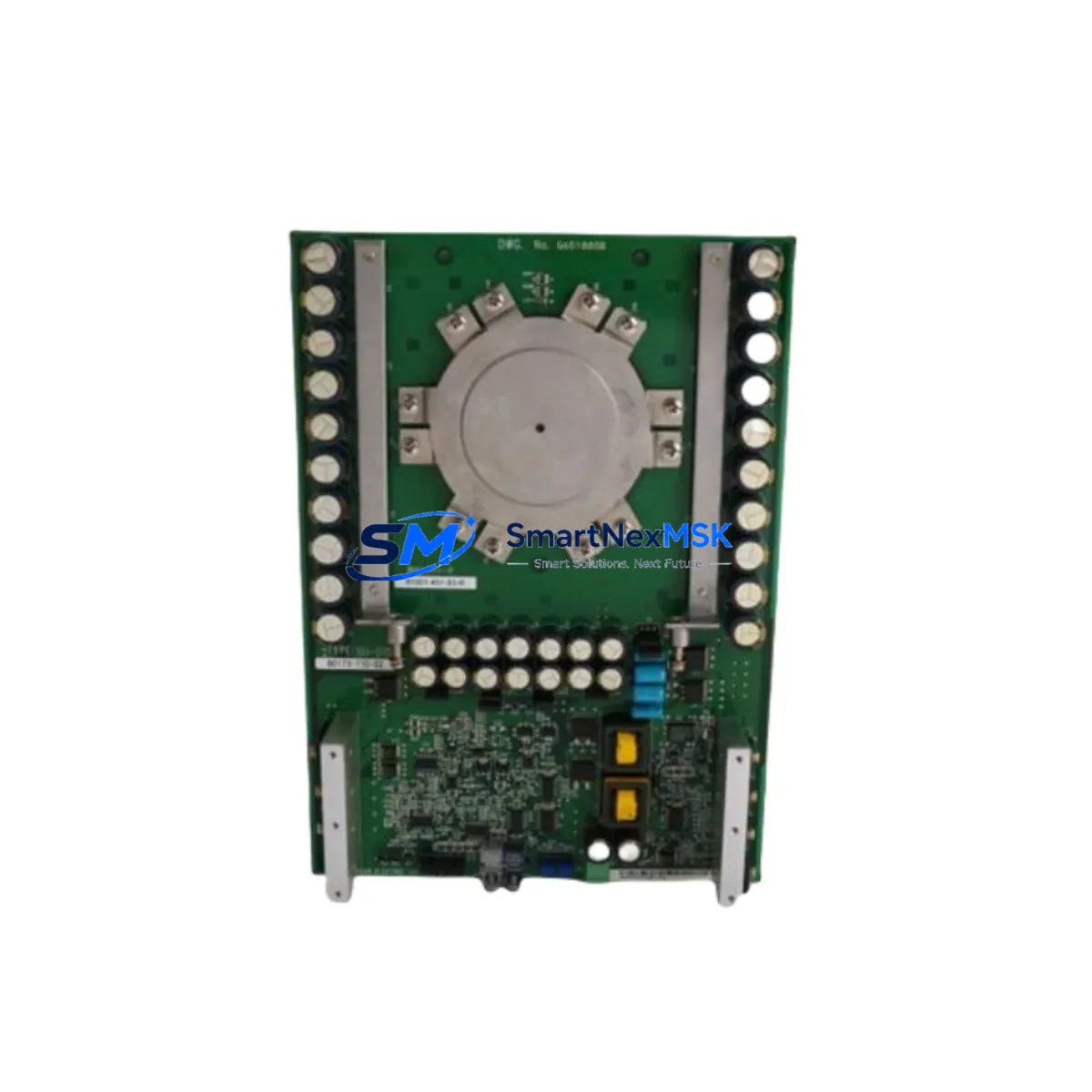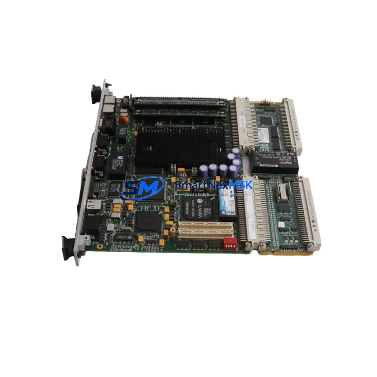
WOODWARD 5466-409 Retrofit-Ready Governor Control Board for 5466 Series Control Systems
The WOODWARD 5466-409 is a retrofit-ready governor PC board engineered for seamless integration into legacy 5466 Series control systems. Whether you are replacing a failed unit, upgrading an aging turbine governor panel, or migrating from a discontinued control platform, the 5466-409 delivers the electrical compatibility, terminal wiring alignment, and firmware-level logic continuity that industrial retrofit projects demand. This board is a direct functional replacement for obsolete WOODWARD governor modules within the 5466 family, making it the preferred choice for power generation facilities, oil and gas compressor stations, and marine propulsion control rooms undertaking planned or emergency modernization.
Upgrade Compatibility Table
| Parameter | Details |
|---|---|
| Compatible Series | WOODWARD 5466 Series Governor Control Systems |
| Direct Replacement For | WOODWARD 5466-409 (OEM), discontinued 5466-4xx variants |
| Terminal Wiring | Pin-for-pin compatible; no rewiring required for standard installations |
| Backplane / Rack Interface | Compatible with 5466 Series card cage and backplane connectors |
| Communication Compatibility | Supports existing analog and discrete I/O signal chains |
| Installation Requirement | Standard DIN rail or card cage mounting; no mechanical modification |
| Retrofit Recommendation | Verify module address jumper settings before power-up |
| Commissioning Focus | Speed reference calibration, droop setting, and actuator output verification |
| Warranty | 12-Month Warranty — covers manufacturing defects and functional failure |
Retrofit Planning for Existing Automation Systems
A successful retrofit of the WOODWARD 5466-409 begins well before the replacement board arrives on site. Engineers should first audit the existing 5466 Series card cage to confirm available slot positions and backplane connector integrity. The power supply module — typically a WOODWARD 5464-series or equivalent regulated DC supply — must be verified to deliver stable voltage within the board’s rated input range, as voltage sag during governor transients can cause spurious trips or erratic speed control behavior.
Terminal block wiring should be documented against the original as-built drawings before any board removal. The 5466-409 uses the same terminal assignments as its predecessor, but field wiring insulation condition and connector torque values should be inspected and corrected during the outage window. Actuator output wiring to the electro-hydraulic or electronic actuator — such as a WOODWARD EG-3P or similar proportional actuator — must be continuity-checked to rule out cable degradation that could mask a board fault.
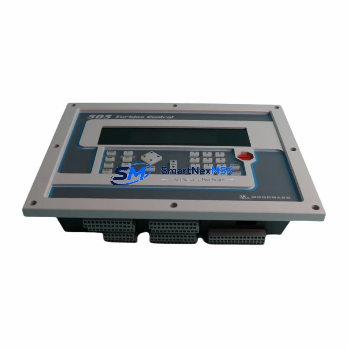
For systems that include a WOODWARD 2301A or 2301D load sharing and speed control module operating in parallel with the 5466 governor, the inter-module communication links and analog reference signals must be re-verified after board swap. Similarly, if the control cabinet integrates a WOODWARD 723 digital governor or a 505 steam turbine controller on the same control bus, the address configuration of the 5466-409 must be set to avoid conflicts. Address jumpers on the replacement board should be matched to the removed unit before installation.
HMI screens connected to the governor system — whether a legacy panel-mounted display or a modern SCADA workstation — should be tested for correct speed, load, and alarm signal reception after commissioning. If the plant uses a Modbus RTU or analog 4–20 mA interface between the governor and the DCS, signal loop integrity must be confirmed with a loop calibrator before returning the unit to automatic control. Programming cables such as the WOODWARD service tool interface cable are recommended for connecting a laptop to verify internal parameter settings and event logs post-installation.
I/O expansion modules installed in adjacent slots of the 5466 card cage — including discrete input modules for start/stop permissives and analog output modules for remote speed reference — should be powered down during board replacement to prevent backplane transients. After installation, bring the system up in manual control mode first, verify actuator response, then transfer to automatic governor control under supervised conditions.
Downtime Control During System Migration
Minimizing unplanned downtime is the primary operational concern when replacing a governor control board in a running facility. The recommended approach is to pre-configure the WOODWARD 5466-409 replacement board on the bench before the scheduled maintenance window. This includes setting all address jumpers, verifying firmware revision compatibility, and performing a bench-level functional check using a WOODWARD service tool to confirm that speed input, actuator output, and alarm relay circuits respond correctly to simulated signals.
During the outage, follow a structured lockout/tagout procedure before removing the failed board. Photograph all wiring connections and record all parameter settings from the existing unit if accessible. The 5466-409’s pin-for-pin terminal compatibility means physical installation is typically completed within 30 minutes, leaving the majority of the maintenance window available for commissioning and verification activities.
After installation, restore power in stages: energize the power supply module first, confirm bus voltage stability, then insert the governor board. Perform a slow-roll speed test before loading the machine to verify that the speed signal chain — from magnetic pickup through the 5466-409 to the actuator — is functioning correctly. Document all as-found and as-left parameter values for the plant maintenance record. This structured approach consistently achieves same-shift return-to-service for governor board replacements in turbine and compressor applications.
Retrofit Support FAQ
Q1: Is the WOODWARD 5466-409 a direct drop-in replacement for the original OEM board?
Yes. The 5466-409 is manufactured to the original WOODWARD specification and is pin-for-pin, terminal-for-terminal compatible with the OEM board. No wiring modifications or mechanical changes are required for standard 5466 Series card cage installations. Verify address jumper settings match the removed unit before power-up.
Q2: What commissioning steps are required after installation?
After physical installation, perform a bench-level actuator output check, verify speed input signal continuity from the magnetic pickup, confirm module address settings, and conduct a supervised slow-roll test before returning the unit to automatic governor control. All parameter settings should be documented as-left for plant records.
Q3: Is the board compatible with both analog and digital control architectures?
The 5466-409 supports the analog and discrete I/O signal architecture of the 5466 Series platform. For systems integrating digital communication links such as Modbus RTU to a DCS or SCADA system, verify that the communication interface module in the card cage is compatible and that signal addresses are correctly mapped before enabling automatic control.
Q4: What does the 12-month warranty cover?
The 12-month warranty covers manufacturing defects and functional failure under normal operating conditions. Each unit undergoes pre-shipment functional testing before dispatch. Warranty claims are supported by our technical team at sales@smartnexmsk.com. Warranty does not cover damage resulting from incorrect installation, overvoltage, or physical mishandling.
© 2026 SMARTNEXMSK. All rights reserved.
Original Source: https://smartnexmsk.com
Contact: sales@smartnexmsk.com | +86 18259474341