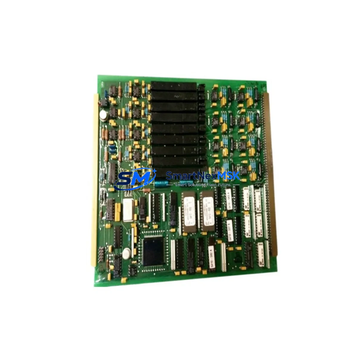
WOODWARD 5500-577 Retrofit-Ready Load Share Module for 5500 Series Control Systems
The WOODWARD 5500-577 Analog Load Share Module is a proven retrofit solution for parallel generator control systems built on the WOODWARD 5500 Series platform. Designed for seamless compatibility with legacy control architectures, this module enables plant engineers and system integrators to modernize aging generator panels without replacing the entire control infrastructure. Whether you are managing a planned upgrade, responding to an end-of-life parts shortage, or recovering from an unplanned failure, the 5500-577 provides a direct, drop-in replacement path with minimal engineering rework.
SMARTNEXMSK maintains verified stock of the 5500-577 and ships globally with full pre-shipment functional testing and a 12-month warranty. Each unit is inspected against original WOODWARD specifications before dispatch, ensuring that your retrofit project starts with a reliable, tested component.
Upgrade Compatibility Table
| Parameter | Details |
|---|---|
| Compatible Series | WOODWARD 5500 Series parallel generator control systems |
| Module Function | Analog Load Share — real and reactive power balancing across paralleled generators |
| Backplane Interface | 5500 Series standard backplane slot; verify slot address assignment before installation |
| Power Supply Requirement | Supplied via backplane; confirm 5500 Series power module (e.g., 5501-470 or equivalent) capacity before adding modules |
| Terminal Wiring | Analog signal terminals; cross-reference existing wiring diagram against 5500-577 terminal layout before reconnection |
| Communication Compatibility | Compatible with WOODWARD 5500 Series communication architecture; no protocol migration required for same-series replacement |
| Replacement Recommendation | Direct replacement for discontinued 5500-577 units; verify firmware revision compatibility with system controller |
| Commissioning Focus | Module address configuration, analog calibration, load share gain adjustment, and parallel bus synchronization verification |
| Warranty | 12 months from date of shipment; covers manufacturing defects and functional failure under normal operating conditions |
| Pre-Shipment Testing | Full functional test performed on every unit before dispatch |
Retrofit Planning for Existing Automation Systems
Retrofitting a 5500 Series generator control panel requires careful coordination across multiple system layers. The 5500-577 Load Share Module does not operate in isolation — it works in concert with the WOODWARD 5500 Series system controller, the power distribution module, I/O expansion modules, and the communication interface cards that link the control panel to the plant SCADA or DCS layer.
Before beginning the retrofit, engineers should audit the existing backplane rack to confirm available slot positions and verify that the installed 5500 Series power supply module has sufficient capacity to support the 5500-577 alongside other installed modules. In multi-generator installations, the load share bus wiring between panels must be inspected and re-terminated according to the 5500-577 terminal diagram to avoid signal interference during parallel operation.
For sites that have previously used the WOODWARD 5500-470 or 5500-475 analog I/O modules in adjacent slots, the wiring harness routing and terminal block assignments should be documented before removal. The 5500-577 shares the same backplane form factor, but analog signal channel assignments differ and must be re-mapped in the system controller configuration. If the site uses a WOODWARD 723 Digital Speed Control or a MicroNet TMR controller as the primary governor, the load share reference signal from the 5500-577 must be verified against the governor’s analog input scaling to ensure correct droop and isochronous load sharing behavior.
Sites running WOODWARD’s MSLC (Master Synchronizer and Load Control) or DSLC (Digital Synchronizer and Load Control) modules in the same control cabinet should confirm that the load share reference voltage range output by the 5500-577 is within the expected input window of those controllers. In installations where a WOODWARD 2301A Load Sharing and Speed Control unit is present, the analog interconnection between the 5500-577 and the 2301A must be re-verified after module replacement to maintain stable parallel operation.
If the control panel includes a WOODWARD 5500 Series HMI display or a third-party operator panel connected via RS-232 or RS-485, the HMI screen assignments for load share percentage, kW output, and reactive power (kVAR) should be validated after the 5500-577 is installed and calibrated. In some legacy installations, HMI tag addresses are hard-coded to specific module slot positions, requiring a configuration update in the HMI project file before the new module is commissioned.
For sites integrating the 5500 Series panel into a broader DCS environment via Modbus RTU or Modbus TCP, the register map for load share data points should be re-confirmed after module replacement, as firmware differences between 5500-577 hardware revisions can affect register offset assignments. Coordination with the DCS engineering team is recommended before the cutover window to avoid data mapping errors that could trigger false alarms in the plant control room.
Downtime Control During System Migration
Minimizing downtime during a 5500-577 module replacement requires a structured pre-outage preparation process. Before the scheduled maintenance window, the site team should capture a full backup of the 5500 Series system controller configuration, including load share gain settings, droop percentages, analog calibration offsets, and communication parameters. This backup ensures that if the replacement module requires reconfiguration, the original parameter set is available for reference and can be restored without relying on memory or incomplete field notes.
Where possible, the replacement 5500-577 should be bench-tested and pre-configured before it arrives on site. SMARTNEXMSK ships each unit with pre-shipment functional verification, but site-specific calibration — particularly analog gain and load share reference scaling — should be completed in a controlled environment before the module enters the live panel. This approach reduces the time the generator is offline and limits the exposure window during which the plant must rely on alternative power sources or reduced generation capacity.
During the physical swap, the original program logic in the system controller is preserved on the backplane and does not need to be reloaded unless the controller itself is being replaced. The 5500-577 is a passive analog module from the controller’s perspective; the controller continues to execute its load sharing algorithm using the new module’s analog outputs once the module is powered and calibrated. This architecture significantly reduces the risk of program logic loss during the replacement procedure and allows the site team to focus on wiring verification, analog calibration, and parallel bus synchronization rather than software recovery.
After installation, a controlled parallel test — bringing the generator online in parallel with the bus before transferring load — is the recommended commissioning sequence. This test validates that the 5500-577 is correctly sharing load with other online generators before the unit is returned to normal automatic operation. The 12-month warranty provided with every SMARTNEXMSK-supplied 5500-577 covers the module through the initial commissioning period and the first year of production operation.
Retrofit Support FAQ
Q: Is the WOODWARD 5500-577 a direct drop-in replacement for my existing failed module?
A: In most 5500 Series installations, yes. The 5500-577 uses the standard 5500 Series backplane form factor and terminal layout. However, you should verify the hardware revision of your existing module against the replacement unit, as analog calibration offsets and firmware behavior can differ between revisions. SMARTNEXMSK can assist with revision identification based on your existing module’s label or part number suffix.
Q: What wiring checks are required before powering up the replacement module?
A: Before energizing the new 5500-577, verify that all analog signal terminals are correctly re-terminated per the 5500-577 wiring diagram, that the load share bus connections between generator panels are intact, and that the backplane power supply module has sufficient capacity. Confirm that no terminal is shorted to chassis ground and that the analog reference signal polarity matches the original installation.
Q: Can the 5500-577 be used in a system that has been partially upgraded to newer WOODWARD controllers?
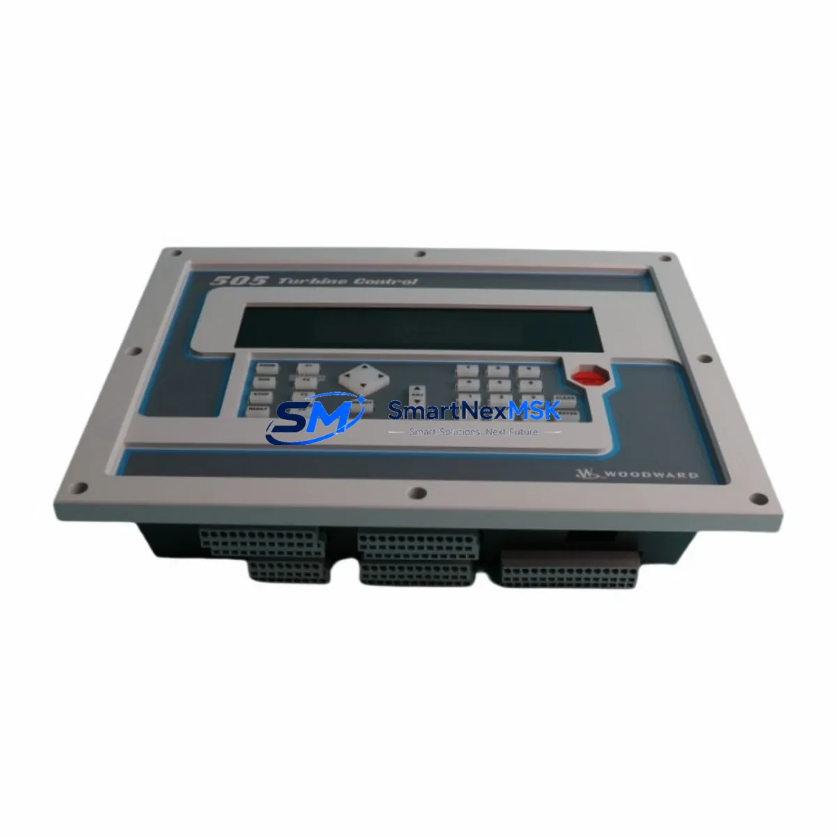
A: The 5500-577 is designed for 5500 Series backplane environments. If your system has been partially upgraded and now includes a MicroNet or 505 Series controller in the same cabinet, the analog interface between the 5500-577 and the newer controller must be validated for signal range compatibility. In mixed-generation control cabinets, a signal conditioning module may be required to bridge the analog output of the 5500-577 to the input specification of the newer controller.
Q: What does the 12-month warranty cover, and what is the claims process?
A: The 12-month warranty covers manufacturing defects and functional failure under normal operating conditions from the date of shipment. It does not cover damage resulting from incorrect installation, overvoltage, or physical impact. To initiate a warranty claim, contact SMARTNEXMSK at sales@smartnexmsk.com with your order number, a description of the failure symptom, and any available site data logs. Replacement or repair will be coordinated within 5 business days of claim receipt.
© 2026 SMARTNEXMSK. All rights reserved.
Original Source: https://smartnexmsk.com
Contact: sales@smartnexmsk.com | +86 18259474341