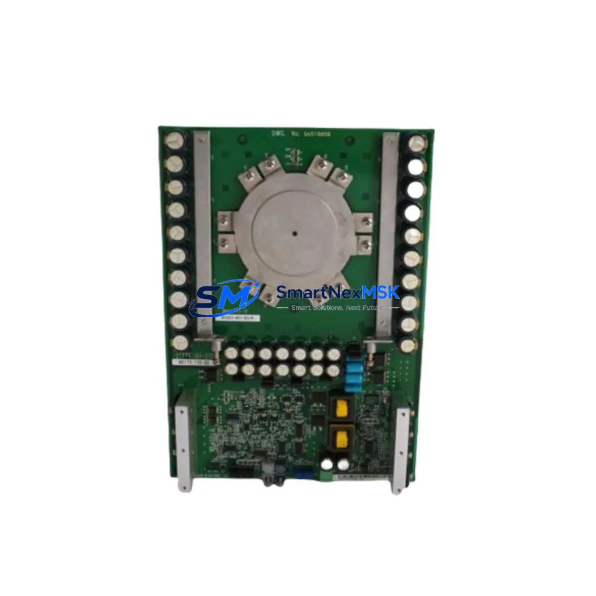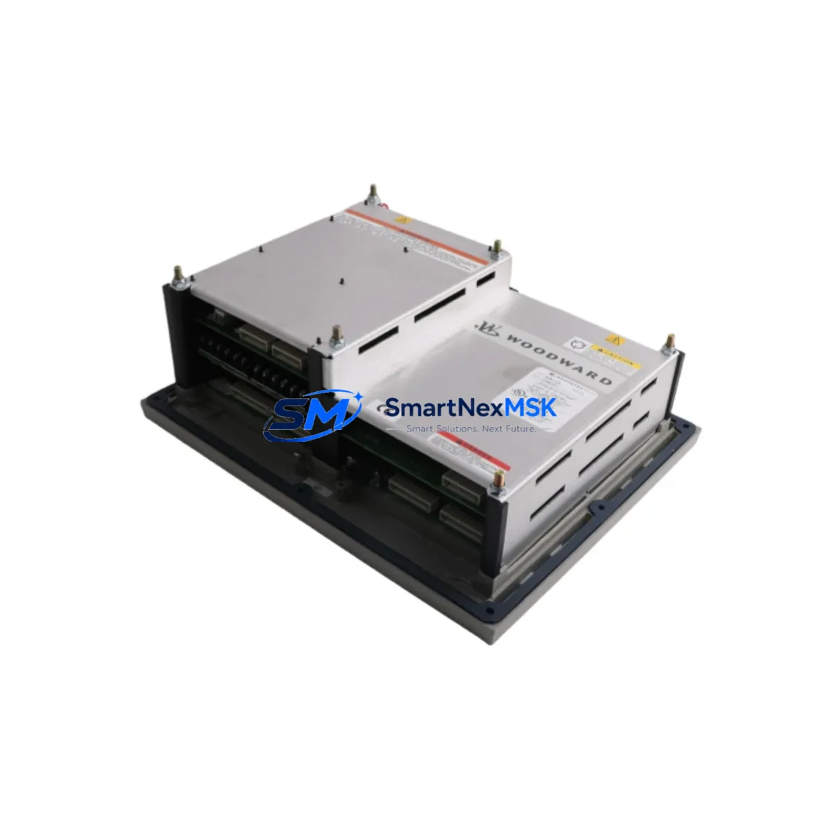
WOODWARD 8406-113 Maintenance-Ready Spare for 8406 Series Automation
The WOODWARD 8406-113 is a governor control module designed for turbine speed regulation and industrial prime mover control within the WOODWARD 8406 Series platform. For maintenance engineers managing aging turbine control systems, this module represents a critical spare that directly impacts plant uptime, process continuity, and safety interlock integrity. Whether you are executing a planned shutdown inspection, responding to an unplanned trip event, or building a strategic spare parts inventory, the 8406-113 is a high-priority line item that should be stocked ahead of demand.
The 8406 Series governor control architecture is widely deployed across gas turbines, steam turbines, diesel gensets, and compressor trains in power generation, oil and gas, and heavy industrial facilities. The 8406-113 module handles speed sensing, droop control, fuel actuator output, and load-sharing logic — functions that are central to both normal operation and emergency response. A failure in this module typically results in a turbine trip, loss of generation capacity, or process shutdown, making rapid replacement the only path to recovery.
When sourcing the 8406-113 as a maintenance spare, procurement engineers should confirm the exact revision level and firmware compatibility with the installed control panel. WOODWARD governor systems often pair the 8406-113 with companion components such as the WOODWARD 8406-114 load control module, the 8406-022 power supply board, and the 8406-176 speed sensor input card. These modules share the same backplane and are frequently replaced together during a corrective maintenance event. Ensuring you have the full set of critical spares on the shelf — rather than just the primary failed component — is the most effective way to compress mean time to repair.
In the field, the 8406-113 interfaces with magnetic pickup units (MPUs) for speed signal input, 4–20 mA actuator outputs to fuel control valves, and discrete I/O for start permissives, trip signals, and load breaker status. Before installing a replacement module, maintenance technicians should verify the integrity of the MPU wiring and shielding, inspect the actuator feedback loop for drift or open circuits, and confirm that the terminal block assignments match the existing panel wiring diagram. The WOODWARD 2301A load sharing and speed control module, if present in the same control cabinet, should also be checked for parameter consistency, as droop settings and load reference values are often coordinated between the two controllers.
For facilities running WOODWARD NetCon or MicroNet control platforms alongside the 8406 Series, communication link integrity between the governor module and the supervisory control layer is a key verification step. The 8406-113 may communicate via hardwired analog signals or through a serial interface depending on the panel configuration. Technicians should confirm that the communication link to the plant DCS or SCADA system is re-established and functioning correctly after module replacement, and that any watchdog or heartbeat signals are active before returning the unit to service.
Planned maintenance intervals for turbine governor systems typically include inspection of the 8406-113 alongside the panel power supply, terminal strips, signal isolators, and relay output cards. A comprehensive inspection should also cover the condition of the control cabinet cooling fans, door seals, and any surge protection devices on the I/O terminals. Replacing a degraded 8406-113 during a scheduled outage — rather than waiting for a failure — eliminates the risk of an unplanned trip and the associated production loss.
All 8406-113 units supplied by SMARTNEXMSK are sourced from verified industrial channels, functionally tested prior to shipment, and covered by a 12-month warranty. Long-term supply continuity is maintained to support facilities with extended maintenance cycles or multi-unit fleets requiring periodic spare replenishment.
Spare Maintenance Table
| Parameter | Specification / Detail |
|---|---|
| Part Number | WOODWARD 8406-113 |
| Series | WOODWARD 8406 Series |
| Function | Governor Control Module — turbine speed regulation, droop control, actuator output |
| Application | Gas turbine, steam turbine, diesel genset, compressor train governor control |
| Speed Input | Magnetic pickup unit (MPU) — passive speed sensor interface |
| Actuator Output | 4–20 mA or PWM fuel actuator control signal |
| Power Supply | Compatible with 8406 Series panel power supply (24 VDC nominal) |
| Installation | Panel-mount, backplane-integrated within 8406 Series control enclosure |
| Communication | Hardwired analog I/O; optional serial interface depending on configuration |
| Operating Environment | Industrial control cabinet; temperature and vibration per WOODWARD 8406 Series spec |
| Compatibility | Direct replacement for WOODWARD 8406-113; compatible with 8406 Series backplane |
| Condition | Tested, verified functional prior to shipment |
| Warranty | 12-Month Warranty — SMARTNEXMSK |
| Origin | USA (WOODWARD) |
| Weight | 4,280 g (approx.) |
Maintenance Planning for Continuous Operation
Effective maintenance planning for turbine governor systems requires a holistic view of the control cabinet, not just the primary failed component. When scheduling a replacement of the WOODWARD 8406-113, maintenance engineers should simultaneously inspect and, where necessary, replace the following components to prevent secondary failures and reduce the probability of a repeat outage.
The WOODWARD 8406-022 power supply board is the first component to verify. A degraded power supply can cause intermittent resets or erratic governor behavior that mimics a faulty control module. Confirm output voltage stability under load before concluding that the 8406-113 is the root cause of a fault. Similarly, the WOODWARD 8406-114 load control module, which coordinates load sharing and import/export control in parallel generation applications, should be inspected for alarm history and parameter integrity during the same maintenance window.
The WOODWARD 8406-176 speed sensor input card conditions the MPU signal before it reaches the governor module. Worn or contaminated MPU connections, or a degraded input card, can produce false overspeed signals or loss-of-speed faults. Inspect the MPU cable, connector, and shielding as part of the replacement procedure. Terminal strips and wiring ferrules throughout the governor panel should also be checked for corrosion, loose connections, and insulation degradation — particularly on the actuator output and discrete I/O circuits.
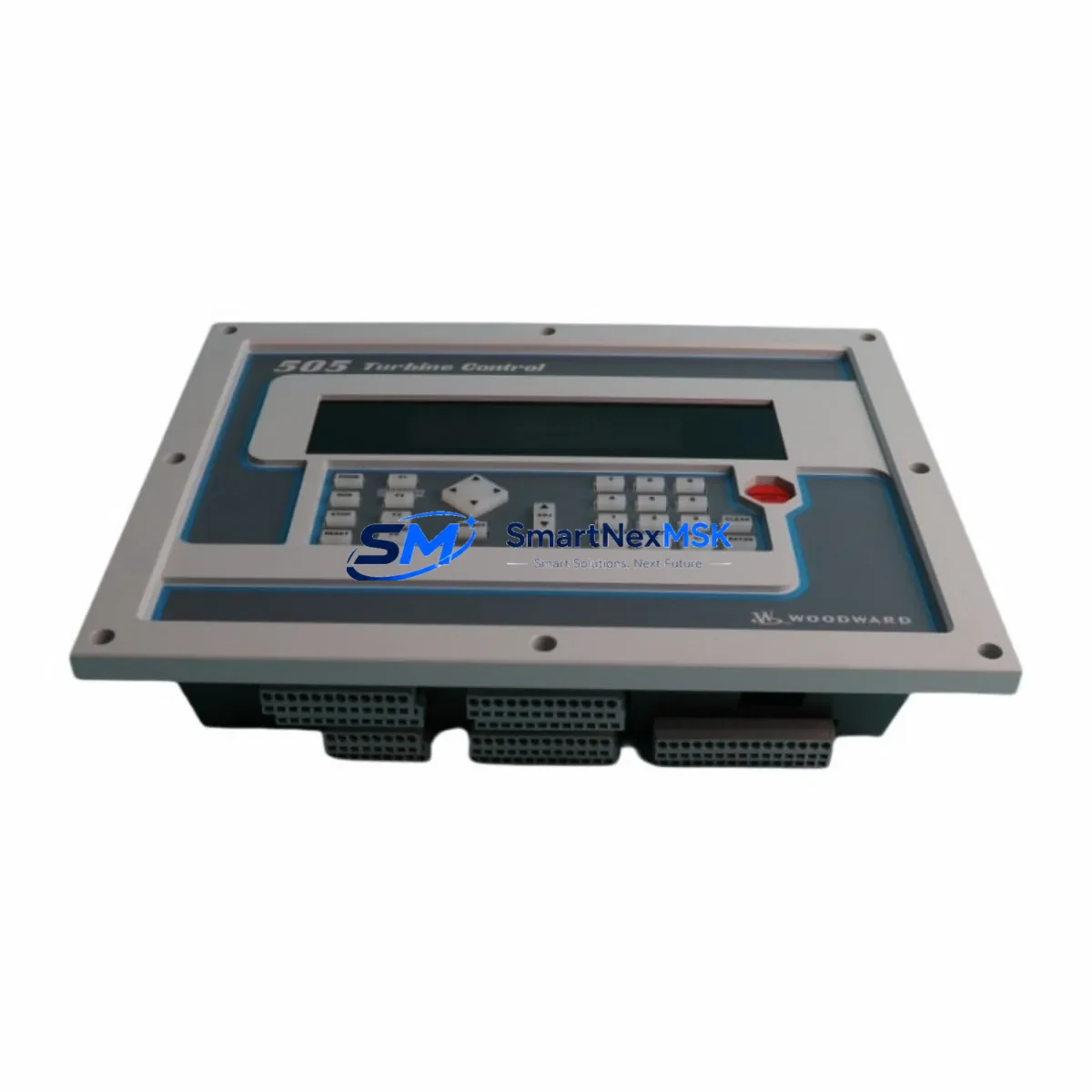
For panels that include a WOODWARD 2301A load sharing and speed control module, verify that droop percentage, speed reference, and load reference settings are consistent with the replacement 8406-113 configuration. Mismatched parameters between the two controllers can cause hunting, instability, or failure to synchronize. If the panel includes a WOODWARD 505 digital governor or WOODWARD MicroNet TMR as a supervisory layer, confirm that the communication link and watchdog handshake are re-established after the module swap.
Signal isolators on the 4–20 mA actuator output circuit should be tested for accuracy and response time. A degraded isolator can introduce offset errors that affect fuel valve positioning and turbine speed stability. Fuse holders and miniature circuit breakers on the panel power distribution rail should be inspected and replaced if showing signs of heat damage or contact wear. Finally, the HMI or operator panel — whether a dedicated WOODWARD display or a third-party touchscreen — should be verified for correct speed, load, and alarm display after the replacement module is commissioned.
Site Replacement Workflow
A structured replacement workflow minimizes downtime and reduces the risk of commissioning errors when installing the WOODWARD 8406-113 in the field.
Step 1 — Pre-Shutdown Preparation: Obtain the panel wiring diagram and the existing governor parameter file. Confirm the replacement module revision level matches the installed unit. Prepare all tools, terminal labels, and a camera for documenting the existing wiring before disconnection.
Step 2 — Safe Isolation: Follow the site lockout/tagout procedure. Isolate the governor panel power supply and confirm zero energy state on all I/O terminals. Remove the MPU signal cable, actuator output wiring, and discrete I/O connections from the 8406-113, labeling each terminal as it is disconnected.
Step 3 — Module Removal and Installation: Remove the faulty 8406-113 from the backplane. Inspect the backplane connector for bent pins or contamination. Seat the replacement module firmly and reconnect all wiring in reverse order, verifying terminal assignments against the wiring diagram.
Step 4 — Parameter Restore and Verification: Restore the governor parameter file to the replacement module using the WOODWARD service tool or front-panel interface. Verify speed reference, droop setting, actuator output calibration, and trip setpoints against the commissioning record.
Step 5 — Functional Test: Restore panel power and perform a no-load functional test. Confirm speed signal input, actuator output response, and discrete I/O status. Check for active alarms and verify communication with any supervisory controller or DCS before returning the turbine to service.
Spare Parts Support FAQ
Q1: Is the WOODWARD 8406-113 a direct drop-in replacement for the installed unit?
Yes, provided the revision level and firmware version are compatible with your panel configuration. SMARTNEXMSK can advise on revision compatibility based on your existing module label information. It is recommended to photograph the installed module label before ordering to confirm an exact match.
Q2: What testing is performed before shipment?
Each 8406-113 unit is functionally tested prior to dispatch to verify power-up behavior, I/O response, and communication interface integrity. A test report is available on request. All units are shipped with protective packaging to prevent transit damage.
Q3: How should the 8406-113 be stored as a long-term spare?
Store in a dry, temperature-controlled environment away from direct sunlight and electromagnetic interference sources. Anti-static packaging should be maintained until installation. Periodic inspection of stored spares — at least annually — is recommended to confirm condition and packaging integrity.
Q4: What does the 12-month warranty cover?
The 12-month warranty covers functional failure under normal operating conditions. It does not cover damage resulting from incorrect installation, overvoltage events, or physical mishandling. SMARTNEXMSK provides replacement or repair support within the warranty period. Contact sales@smartnexmsk.com for warranty claims and RMA procedures.
© 2026 SMARTNEXMSK. All rights reserved.
Original Source: https://smartnexmsk.com
Contact: sales@smartnexmsk.com | +86 18259474341