WOODWARD 8440-1800 Spare for EasyGen-320 Automation: Spare Replacement & Industrial Downtime Risk Control
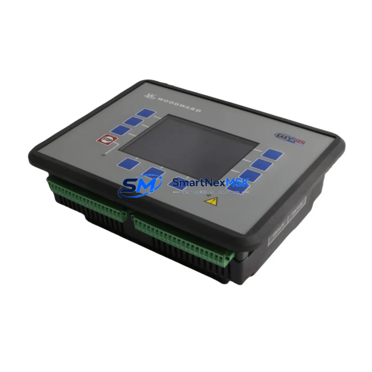
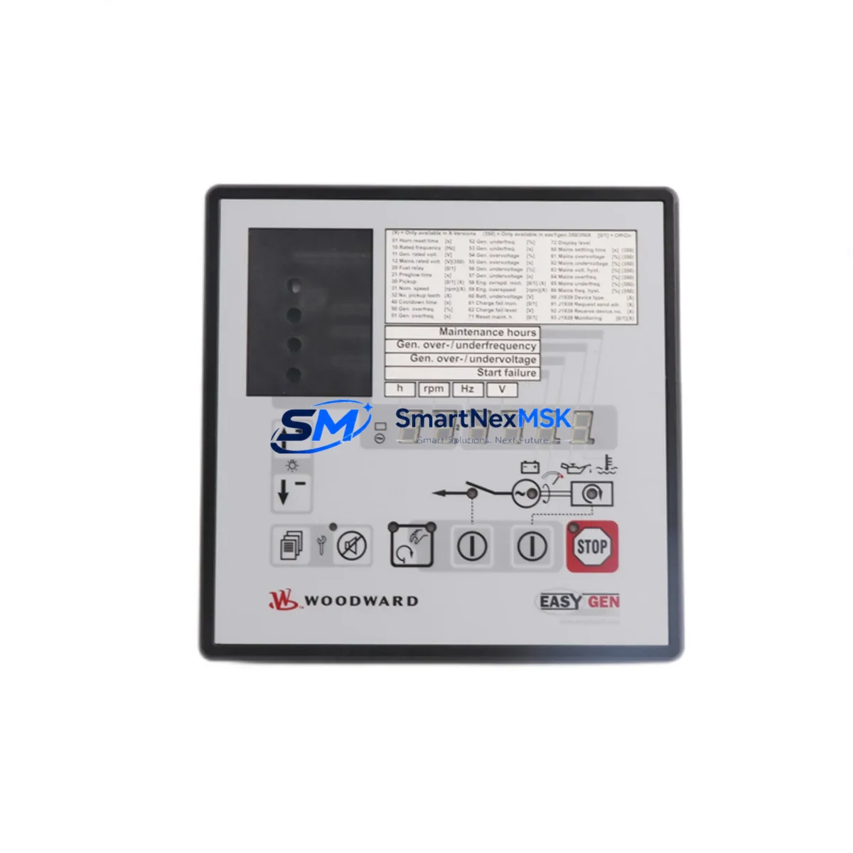
The WOODWARD 8440-1800 is the core Genset Management Unit (GMU) of the EasyGen-320 series, designed for single genset control applications in power generation, oil & gas, marine auxiliary, and industrial standby systems. When this module fails or reaches end-of-life, the entire generator control loop is disrupted — leading to unplanned downtime, failed automatic start sequences, and loss of load management capability. Sourcing a maintenance-ready spare before failure occurs is the most effective strategy for continuous operation.
At SMARTNEXMSK, every WOODWARD 8440-1800 unit is sourced from verified supply channels, inspected against original factory specifications, and tested before shipment. We support maintenance engineers and procurement teams with long-term spare parts supply, 12-month warranty coverage, and fast worldwide delivery — ensuring your EasyGen-320 system stays operational through planned maintenance cycles and emergency replacement scenarios alike.
Spare Maintenance Table
| Parameter | Specification |
|---|---|
| Part Number / SKU | 8440-1800 (EasyGen-320) |
| Manufacturer | WOODWARD |
| Series | EasyGen-320 |
| Function | Single Genset Management Unit (GMU) |
| Supply Voltage | 8–32 VDC (wide-range DC input) |
| Digital Inputs | Configurable discrete inputs for start/stop, fault, and mode selection |
| Analog Inputs | Generator voltage, current, frequency sensing |
| Communication | RS-485 / Modbus RTU |
| Display | Integrated LCD with keypad interface |
| Protection Functions | Over/under voltage, over/under frequency, overcurrent, reverse power |
| Operating Temperature | -20°C to +70°C |
| Mounting | Panel-mount, DIN rail compatible enclosure |
| Compatibility | Drop-in replacement for EasyGen-320 series installations |
| Application Environment | Power generation, oil & gas, marine auxiliary, industrial standby |
| Condition | Original spare, tested before shipment |
| Warranty | 12 Months |
| Delivery | Fast worldwide shipping; DHL / FedEx / UPS available |
Maintenance Planning for Continuous Operation
When replacing the WOODWARD 8440-1800 GMU in an EasyGen-320 control panel, a thorough maintenance inspection of the surrounding electrical system is essential to prevent repeat failures and ensure a clean restart. Maintenance engineers should treat this replacement as an opportunity to audit the full generator control cabinet.
Power Supply Integrity: Verify the 24 VDC panel power supply feeding the GMU — a degraded or undersized supply is a common root cause of GMU resets and communication faults. Units such as the WOODWARD EasyGen-300 series power supply module or equivalent DIN-rail SMPS should be load-tested before reconnecting the new 8440-1800.
Wiring and Terminal Blocks: Inspect all terminal block connections on the GMU’s discrete input and output wiring. Loose or corroded terminals on Phoenix Contact or Weidmüller-style terminal strips are a frequent source of intermittent faults in genset control circuits. Re-torque all connections to specification and replace any discolored or heat-damaged terminals.
Current Transformers and Voltage Sensing: The 8440-1800 relies on accurate CT and PT inputs for protection functions. Verify that the current transformers (typically 5A secondary) and voltage sensing wiring are intact and correctly phased. A misconnected CT can cause nuisance reverse-power trips immediately after replacement.
Digital I/O and Relay Outputs: Test all discrete input signals — remote start, emergency stop, mode selection — and verify relay output contacts for AMF (Automatic Mains Failure) and load transfer functions. Relay contacts in the control circuit, including intermediate relays and contactor auxiliary contacts, should be checked for wear and contact resistance.
RS-485 Communication Bus: If the EasyGen-320 is networked via Modbus RTU to a SCADA system, PLC, or HMI panel (such as a WOODWARD InPower service tool or a third-party Modbus master), verify bus termination resistors and cable shielding continuity. A damaged RS-485 transceiver or missing termination is a common cause of communication loss after module replacement.
Speed and Magnetic Pickup: The magnetic pickup (MPU) sensor feeding engine speed to the GMU should be inspected for gap distance and signal amplitude. A worn or misaligned MPU will cause erratic speed readings and failed start sequences — replace proactively if the unit has been in service for more than 5 years.
Battery and Charger Circuit: For standby genset applications, inspect the battery charger module and battery bank condition. A weak battery will cause failed cranking sequences that may be misdiagnosed as GMU faults. Battery voltage under load and charger float voltage should both be within specification.
HMI and Operator Panel: If the installation includes a remote annunciator panel or operator HMI, verify that the communication link to the new 8440-1800 is re-established after replacement and that all alarm setpoints are correctly configured in the new unit’s parameter set.
Maintaining a stocked spare of the 8440-1800 alongside related components — including a spare MPU sensor, a set of control fuses, and a backup RS-485 communication cable — reduces mean time to repair (MTTR) from hours to minutes in emergency scenarios.
Site Replacement Workflow
Step 1 — Pre-Replacement Documentation: Before removing the existing 8440-1800, use the WOODWARD InPower software or the front-panel keypad to export or record all parameter settings, setpoints, and protection thresholds. This ensures the replacement unit can be configured identically without relying on memory or outdated paper records.
Step 2 — Safe Isolation: Isolate the generator from the load bus and disable the automatic start function. De-energize the control panel and verify zero voltage on all terminals before disconnecting the GMU. Follow site-specific LOTO (Lockout/Tagout) procedures.
Step 3 — Module Removal and Inspection: Remove the 8440-1800 and inspect the panel interior for signs of moisture ingress, insulation breakdown, or rodent damage. Clean the panel interior and verify that the mounting surface and connector pins are undamaged before installing the replacement unit.
Step 4 — Installation and Parameter Restore: Install the new WOODWARD 8440-1800 and reconnect all wiring per the original wiring diagram. Restore all parameters from the pre-replacement record. Verify communication link to any connected SCADA or HMI system.
Step 5 — Functional Test Before Return to Service: Perform a no-load test start sequence to verify engine start, speed stabilization, voltage build-up, and protection relay operation. Confirm Modbus communication is active and all alarm channels are clear before returning the generator to automatic standby mode.
This structured workflow minimizes downtime, eliminates configuration errors, and ensures the replacement 8440-1800 performs identically to the original — maintaining system compatibility and regulatory compliance for critical power applications.
Spare Parts Support FAQ
Q1: Is the WOODWARD 8440-1800 a direct drop-in replacement for existing EasyGen-320 installations?
Yes. The 8440-1800 is the standard GMU for the EasyGen-320 series and is a direct mechanical and electrical replacement for units of the same part number. Parameter configuration must be restored from site records or re-entered via InPower software or the front-panel interface. No hardware modification is required for standard installations.
Q2: What does the 12-month warranty cover, and what is the claims process?
All WOODWARD 8440-1800 units supplied by SMARTNEXMSK carry a 12-month warranty covering manufacturing defects and functional failures under normal operating conditions. Each unit is tested before shipment. In the event of a warranty claim, contact sales@smartnexmsk.com with the order reference and a description of the fault. We will arrange replacement or repair with priority handling.
Q3: How should the 8440-1800 be stored as a long-term spare?
Store in original anti-static packaging in a dry, temperature-controlled environment (recommended: 10°C–35°C, <70% RH non-condensing). Avoid storage near strong magnetic fields or high-vibration areas. Inspect the unit annually for any signs of physical damage or connector corrosion. Properly stored, the 8440-1800 has a shelf life of 5+ years without functional degradation.
Q4: Can SMARTNEXMSK supply multiple units for a fleet or multi-site spare parts program?
Yes. We support bulk procurement for maintenance departments managing multiple genset installations. Volume pricing, consolidated shipping, and staggered delivery schedules are available. Contact sales@smartnexmsk.com or call +86 18259474341 to discuss your spare parts program requirements.
© 2026 SMARTNEXMSK. All rights reserved.
Original Source: https://smartnexmsk.com
Contact: sales@smartnexmsk.com | +86 18259474341