XYCOM XVME-531 Retrofit-Ready Power Supply for XVME Series Control Systems
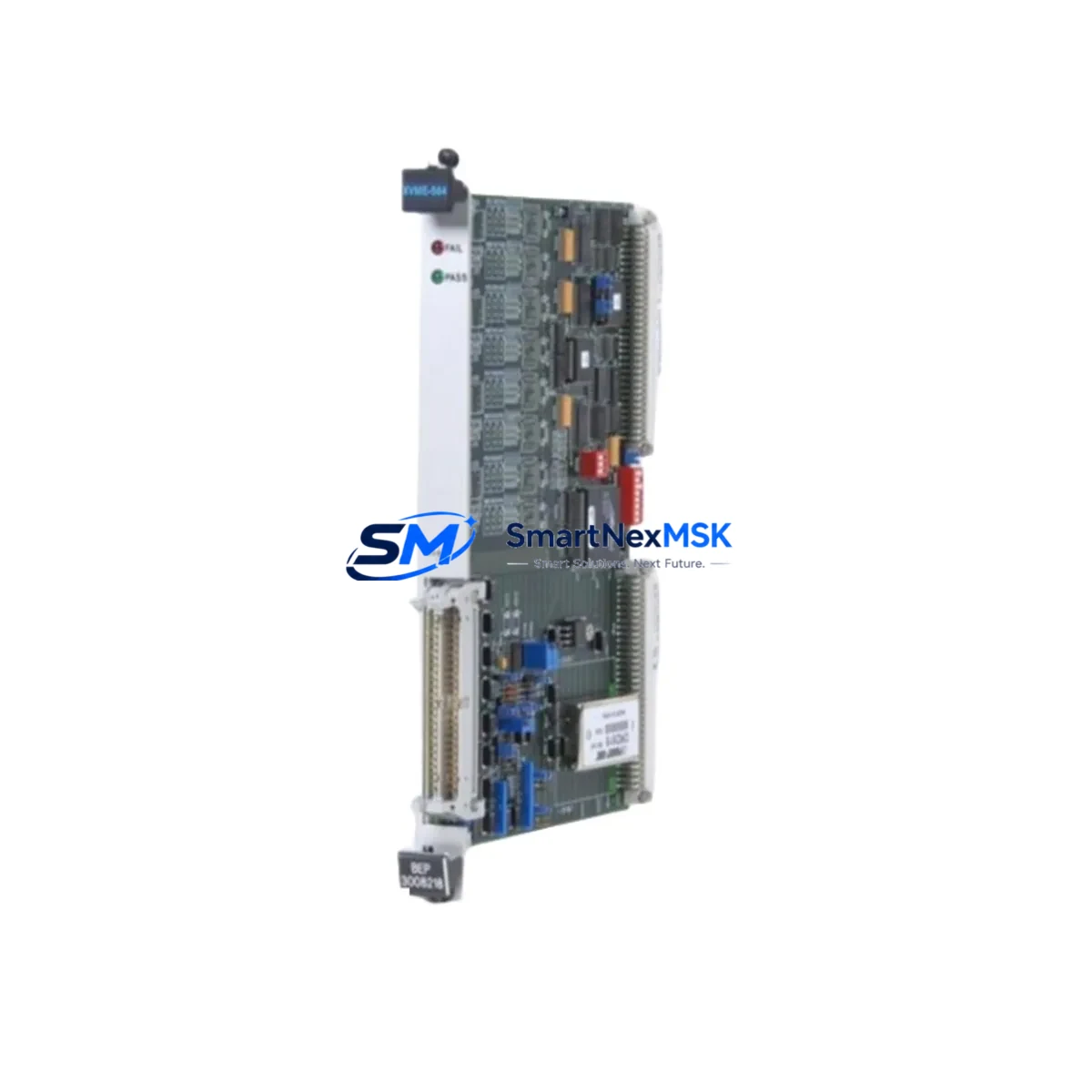
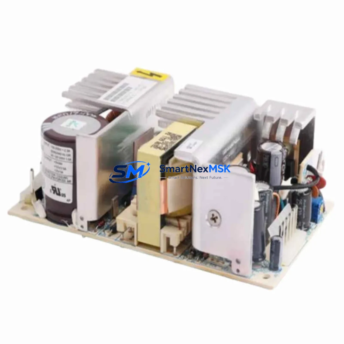
The XYCOM XVME-531 is a VMEbus-compliant power supply module engineered for seamless integration into legacy XVME Series control architectures. As industrial facilities face increasing pressure to modernize aging automation infrastructure without full system replacement, the XVME-531 has become a critical component in retrofit projects across process control, discrete manufacturing, and utility automation environments. Whether you are replacing a failed unit on an active production line, upgrading a control cabinet to extend service life, or migrating from an end-of-life platform, the XVME-531 delivers the electrical compatibility and mechanical fit required for a low-risk, minimum-downtime changeover.
Sourced from verified inventory channels and subjected to pre-shipment functional testing, each XVME-531 unit shipped by SMARTNEXMSK is backed by a 12-month warranty covering manufacturing defects and operational failures under normal industrial service conditions. Our technical team supports customers through wiring verification, slot assignment, backplane compatibility checks, and post-installation commissioning guidance.
Upgrade Compatibility Table
| Parameter | XVME-531 Specification | Retrofit Notes |
|---|---|---|
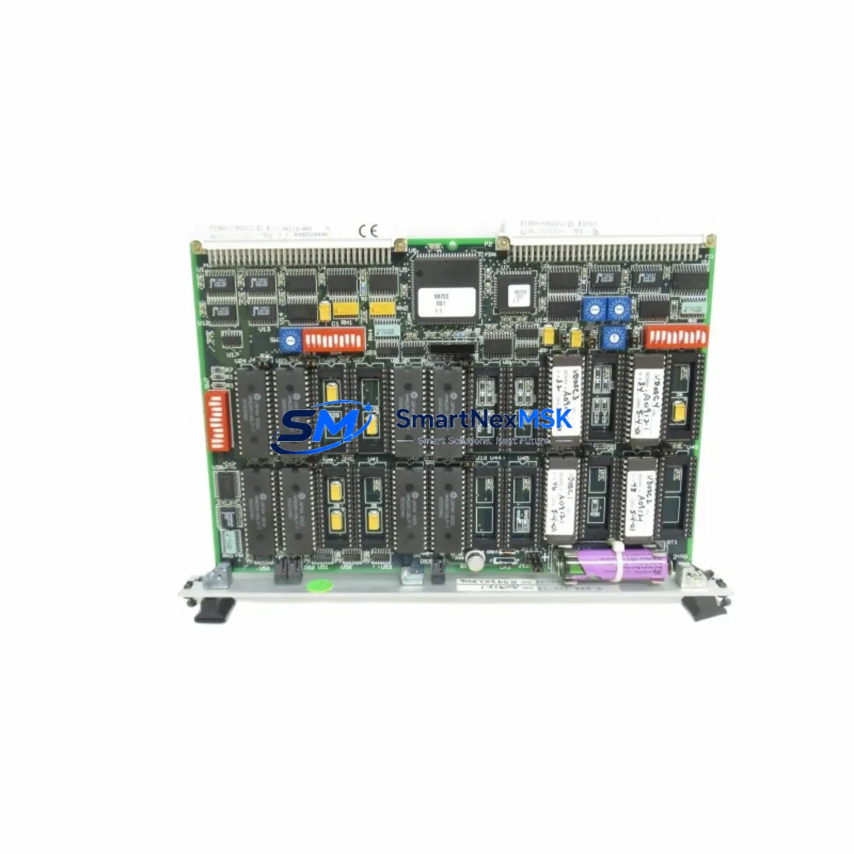
| Bus Standard | VMEbus (IEEE 1014) | Compatible with all standard VME64 and VME64x backplanes |
| Form Factor | 6U VME single-slot | Direct mechanical fit in XVME Series chassis; no bracket modification required |
| Output Voltages | +5 VDC, ±12 VDC | Verify load capacity against total chassis draw before installation |
| Terminal Wiring | Standard AC input terminal block | Retain original wiring harness; confirm conductor gauge and torque spec |
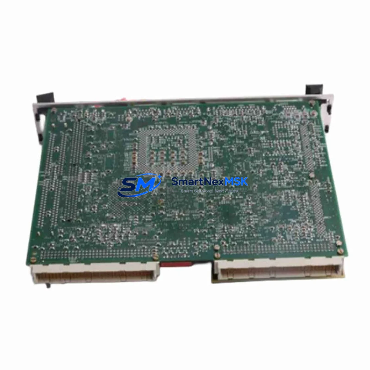
| Backplane Interface | P1/P2 VME connector | Inspect P1/P2 pins on chassis backplane for corrosion before seating module |
| Module Addressing | Not address-mapped (power supply) | No slot address configuration required; verify chassis slot assignment per rack layout drawing |
| Communication Compatibility | Passive power role; no protocol dependency | Compatible with XVME-010, XVME-050 system controllers and associated communication modules |
| Replacement Scope | Drop-in for XVME-531 and functionally equivalent XVME-series PSU variants | Confirm OEM part number cross-reference with SMARTNEXMSK before ordering |
| Commissioning | Power-on self-test via front-panel LED indicators | Verify all rail voltages under load before enabling downstream I/O modules |
| Warranty | 12 months from shipment date — covers manufacturing defects and operational failure under normal industrial service conditions | |
Retrofit Planning for Existing Automation Systems
A successful XVME-531 retrofit begins well before the module arrives on site. Engineers responsible for the changeover must first audit the existing control cabinet to document the full power budget of the VME chassis. In a typical XVME Series rack, the power supply supports a mix of processor boards such as the XVME-010 Single-Board Computer, analog I/O modules like the XVME-566 Analog Input Module, and digital I/O cards including the XVME-240 Digital I/O Module. Each of these draws current from the +5 VDC and ±12 VDC rails, and the aggregate load must remain within the XVME-531’s rated output capacity to ensure stable operation after replacement.
Terminal wiring is the next critical checkpoint. The incoming AC supply conductors connected to the original power supply must be inspected for insulation condition, conductor cross-section, and terminal torque. In older installations, terminal blocks may show signs of oxidation or thermal stress from years of operation. It is advisable to replace terminal ferrules and re-torque all connections to the manufacturer’s specification during the retrofit window rather than reusing aged terminations.
Backplane integrity is equally important. Before inserting the XVME-531, technicians should visually inspect the VME backplane P1 and P2 connectors for bent pins, contamination, or corrosion — particularly in environments with high humidity or airborne particulates. If the chassis also houses a XVME-050 VMEbus Extender or a XVME-400 Series Communication Controller, confirm that the backplane power distribution traces are intact and that no prior fault event has caused localized damage.
For systems that include an XVME-688 Ethernet Communication Module or legacy serial communication cards interfacing with SCADA or DCS platforms, the power supply replacement must be coordinated with the control room team to ensure that communication links are gracefully suspended before power is removed. Abrupt power loss to active communication modules can corrupt configuration tables or trigger fault states in connected HMI stations that require manual reset.
Where the control system interfaces with a XVME-972 Single-Board Computer running real-time operating system tasks, it is essential to perform a controlled shutdown sequence — saving all volatile program data and flushing communication buffers — before de-energizing the chassis. After the XVME-531 is installed and power is restored, the SBC should be allowed to complete its full boot sequence and self-diagnostics before I/O modules are re-enabled. Any XVME-560 Analog Output Module driving field actuators should be held in a safe state during this period to prevent unintended process movement.
Programming compatibility is not a concern for a power supply replacement in isolation, but if the retrofit is part of a broader platform migration — for example, transitioning from a VMEbus architecture to a modern rack-based PLC platform — then program logic conversion, HMI screen re-mapping, and I/O address reassignment must be planned in parallel. SMARTNEXMSK can supply the XVME-531 as a bridge solution to stabilize the existing system while the migration project is executed in phases, minimizing the risk of a full cutover under time pressure.
Downtime Control During System Migration
Minimizing unplanned downtime is the primary operational constraint in any live-system retrofit. For the XVME-531 replacement, the recommended approach is to pre-stage the new module in the control room at least 24 hours before the scheduled maintenance window. This allows the module to thermally equilibrate to the ambient environment and gives the engineering team time to verify the unit against the original part number, inspect the P1/P2 connector condition, and confirm that all front-panel indicators are functional before the chassis is de-energized.
During the maintenance window itself, the sequence should follow a structured lockout/tagout procedure: isolate the AC supply to the VME chassis, document the current state of all I/O module status LEDs, remove the failed or end-of-life XVME-531, seat the replacement module firmly into the chassis slot, restore AC power, and verify all output rail voltages before re-enabling the system controller. The entire hot-swap sequence for an experienced technician familiar with the XVME chassis architecture typically requires 15 to 30 minutes of active work time, excluding pre-staging and post-commissioning verification.
To protect original program logic, ensure that the XVME-010 or equivalent system controller has its battery-backed SRAM intact and that no forced I/O states are active in the PLC program at the time of power removal. If the system uses a XVME-400 Series communication controller to maintain a live link to a DCS or SCADA host, coordinate with the control room operator to place the relevant control loops in manual mode before initiating the power supply swap. This preserves field control continuity and prevents spurious alarms from propagating to the operations team during the changeover.
Post-installation, perform a full I/O scan and compare live field values against the pre-shutdown baseline to confirm that all modules have resumed normal operation. Document the replacement event in the plant maintenance management system with the new module’s serial number, installation date, and warranty expiration date for future reference.
Retrofit Support FAQ
Q1: Is the XVME-531 a direct drop-in replacement for the original XYCOM unit?
Yes. The XVME-531 supplied by SMARTNEXMSK is sourced to match the original XYCOM part number and mechanical form factor. It is designed for direct installation into the same VME chassis slot without modification to the backplane, wiring harness, or chassis enclosure. We recommend confirming the exact revision level and output rating against your system’s power budget before ordering.
Q2: What commissioning steps are required after installation?
After seating the module and restoring AC power, verify all output rail voltages (+5 VDC, ±12 VDC) using a calibrated multimeter at the backplane test points before enabling the system controller. Confirm that all front-panel LED indicators show normal status. Allow the system controller to complete its boot sequence and self-diagnostics, then perform a full I/O scan to verify that all downstream modules — including analog I/O, digital I/O, and communication cards — have resumed normal operation.
Q3: Can the XVME-531 be used in a chassis that also contains third-party VMEbus modules?
Yes, provided the third-party modules comply with the VMEbus IEEE 1014 standard and their combined current draw does not exceed the XVME-531’s rated output capacity. Review the power consumption specifications of all installed modules and calculate the total chassis load on each voltage rail before installation. Contact SMARTNEXMSK technical support if you require assistance with power budget calculations.
Q4: What does the 12-month warranty cover, and how is a warranty claim initiated?
The 12-month warranty covers manufacturing defects and operational failures occurring under normal industrial service conditions from the shipment date. It does not cover damage resulting from incorrect installation, overvoltage events, physical impact, or operation outside the module’s rated environmental specifications. To initiate a warranty claim, contact SMARTNEXMSK at sales@smartnexmsk.com with the order number, module serial number, and a description of the fault. Our team will arrange return authorization and replacement or repair within the warranty period.
© 2026 SMARTNEXMSK. All rights reserved.
Original Source: https://smartnexmsk.com
Contact: sales@smartnexmsk.com | +86 18259474341