Xycom XVME-564 Maintenance-Ready Spare for XVME Automation
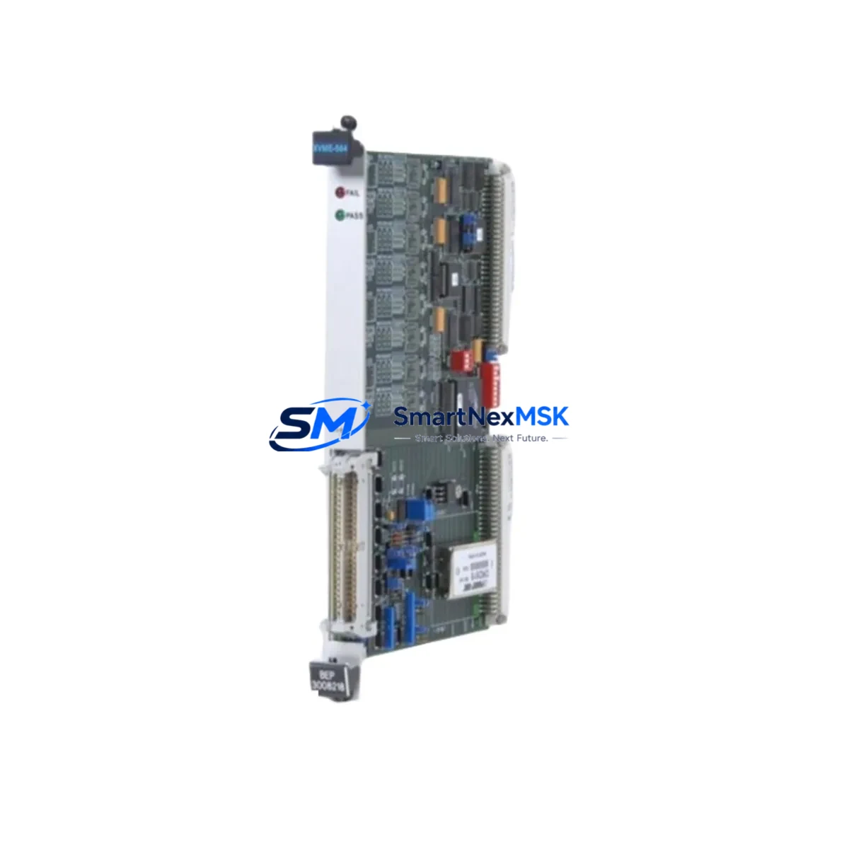
The Xycom XVME-564 is an original VMEbus analog input module engineered for high-reliability industrial automation environments. As a maintenance-ready spare, it is sourced, inspected, and tested to support rapid replacement in VME-based control systems — minimizing unplanned downtime and protecting continuous production operations. Whether you are managing a scheduled overhaul, responding to an emergency fault, or building a strategic spare parts inventory, the XVME-564 delivers the compatibility, signal integrity, and long-term availability that maintenance and procurement engineers depend on.
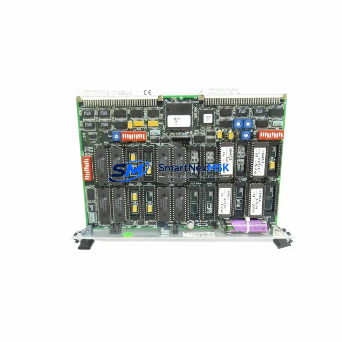
Designed for the XVME product family, this analog input module integrates directly into VMEbus backplane architectures commonly found in process control, motion control, and legacy DCS/SCADA systems. Its multi-channel analog input capability supports precise signal acquisition from field sensors, transducers, and transmitters — making it a critical component in any control cabinet where analog measurement accuracy is non-negotiable.
Every unit shipped undergoes functional verification and burn-in testing prior to dispatch. Each XVME-564 is backed by a 12-month warranty, providing procurement teams with the confidence to stock this module as a long-term replacement asset for aging XVME-based infrastructure.
Spare Maintenance Table
| Parameter | Specification / Detail |
|---|---|
| Part Number / SKU | XVME-564 |
| Brand | Xycom |
| Series | XVME (VMEbus Module Series) |
| Module Type | Analog Input Module |
| Bus Standard | VMEbus (IEEE 1014) |
| Input Channels | Multi-channel analog input (voltage/current) |
| Signal Range | ±10V / 0–10V / 4–20mA (configurable per channel) |
| Resolution | 12-bit or 16-bit ADC (model-dependent) |
| Compatibility | XVME series VMEbus backplanes; Xycom XVME-500/550/560 family systems |
| Operating Temperature | 0°C to +60°C (industrial grade) |
| Mounting | VMEbus single-slot, 6U form factor |
| Power Supply | +5V DC via VMEbus backplane |
| Application Environment | Process control, motion control, legacy DCS/SCADA, industrial automation |
| Condition | Original / Genuine — tested and verified |
| Maintenance Recommendation | Inspect backplane connectors, verify analog signal calibration after installation |
| Warranty | 12 Months |
| Shipping | Tested before dispatch; ESD-safe packaging |
Maintenance Planning for Continuous Operation
When replacing the XVME-564 analog input module during a planned or emergency maintenance event, a thorough inspection of the surrounding control cabinet components is essential to ensure system integrity and prevent repeat failures. Maintenance engineers should begin by verifying the VMEbus backplane — including the XVME-010 or XVME-012 backplane assemblies — for damaged bus connectors, oxidized contacts, or bent pins that could compromise signal transmission after the new module is seated.
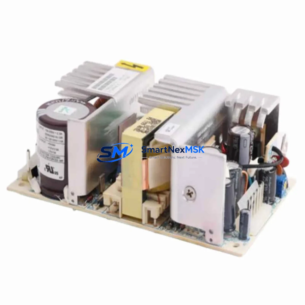
The +5V DC power supply feeding the VMEbus rack should be load-tested and its output voltage confirmed within tolerance. Aging or undersized power supply modules are a common root cause of intermittent analog input faults and should be treated as a co-replacement candidate alongside the XVME-564. Similarly, the XVME-540 or XVME-550 CPU modules sharing the same backplane should be inspected for firmware currency and communication health before the system is returned to service.
Field wiring termination at the analog input front panel connector deserves careful attention. Loose screw terminals, corroded field wiring, or improperly shielded signal cables can introduce noise into the analog measurement chain, masking the true performance of a newly installed XVME-564. Signal isolators or signal conditioners installed between field transmitters and the module input should also be verified for correct output range and calibration.
For systems using the XVME-560 or XVME-566 family in adjacent slots, confirm that inter-module communication and interrupt lines are functioning correctly after the replacement. I/O expansion modules, relay output cards, and digital I/O modules in the same rack should be visually inspected for signs of heat stress or connector fatigue. Fuse holders and circuit protection devices on the analog input signal lines should be checked and replaced if continuity is marginal.
Where the XVME-564 interfaces with an HMI or operator workstation via a VMEbus communication bridge or serial interface module, verify that the data acquisition tags and engineering unit scaling remain correctly configured after the module swap. Procurement engineers building a strategic spare parts inventory for XVME-based systems should consider stocking the XVME-564 alongside compatible CPU modules, power supply units, and backplane assemblies to support full system recovery from a single point of failure.
Site Replacement Workflow
Step 1 — Isolation & Safety: De-energize the VMEbus rack following site lockout/tagout procedures. Confirm zero voltage on the backplane power rails before handling any module.
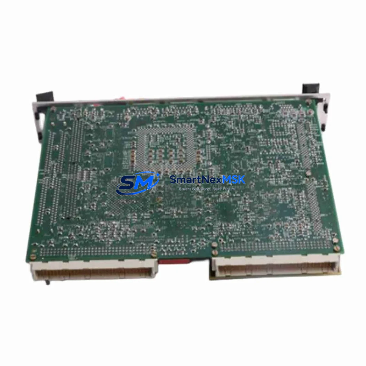
Step 2 — Module Extraction: Release the XVME-564 ejector levers and carefully extract the module from its slot. Avoid flexing the PCB. Place the removed module in an ESD-safe bag for return or failure analysis.
Step 3 — Backplane Inspection: Inspect the vacated slot’s backplane connector for bent pins, debris, or corrosion. Clean with appropriate contact cleaner if required.
Step 4 — Replacement Installation: Insert the new XVME-564 into the correct slot, ensuring full engagement with the VMEbus P1/P2 connectors. Secure the front panel retaining screws.
Step 5 — Power-Up & Verification: Re-energize the rack and confirm the module is recognized by the host CPU. Verify analog input channel readings against known reference signals or calibration sources.
Step 6 — System Return to Service: Confirm all analog tags are reading correctly in the SCADA/DCS/HMI. Document the replacement in the site maintenance log and update the spare parts inventory record.
This workflow supports direct replacement of legacy XVME-564 units without requiring system reconfiguration, preserving full backward compatibility with existing software and I/O mapping.
Spare Parts Support FAQ
Q1: Is the XVME-564 a direct drop-in replacement for the original Xycom module?
Yes. The XVME-564 supplied by SMARTNEXMSK is an original Xycom module that installs directly into any compatible XVME VMEbus backplane slot without hardware or software modification. Compatibility with the XVME series architecture is preserved.
Q2: What testing is performed before shipment?
Every XVME-564 undergoes functional power-on testing and analog channel verification prior to dispatch. Units are shipped in ESD-safe packaging with a test confirmation record. The 12-month warranty covers functional defects identified after installation.
Q3: How should I manage long-term spare parts inventory for XVME-based systems?
For systems where the XVME platform is no longer in active production, we recommend maintaining a minimum of one XVME-564 per installed rack as a hot-standby spare. Pairing this with a stocked CPU module and power supply unit provides full recovery capability from the most common single-point failures in aging VMEbus control systems.
Q4: Can compatibility be verified before purchase for my specific system configuration?
Yes. Contact our technical team with your system model, backplane part number, and slot configuration. We will confirm compatibility and, where applicable, cross-reference against alternative XVME analog input modules to ensure the correct replacement is supplied.
© 2026 SMARTNEXMSK. All rights reserved.
Original Source: https://smartnexmsk.com
Contact: sales@smartnexmsk.com | +86 18259474341