YASKAWA CPS-150F Maintenance-Ready Spare for MP Series Automation
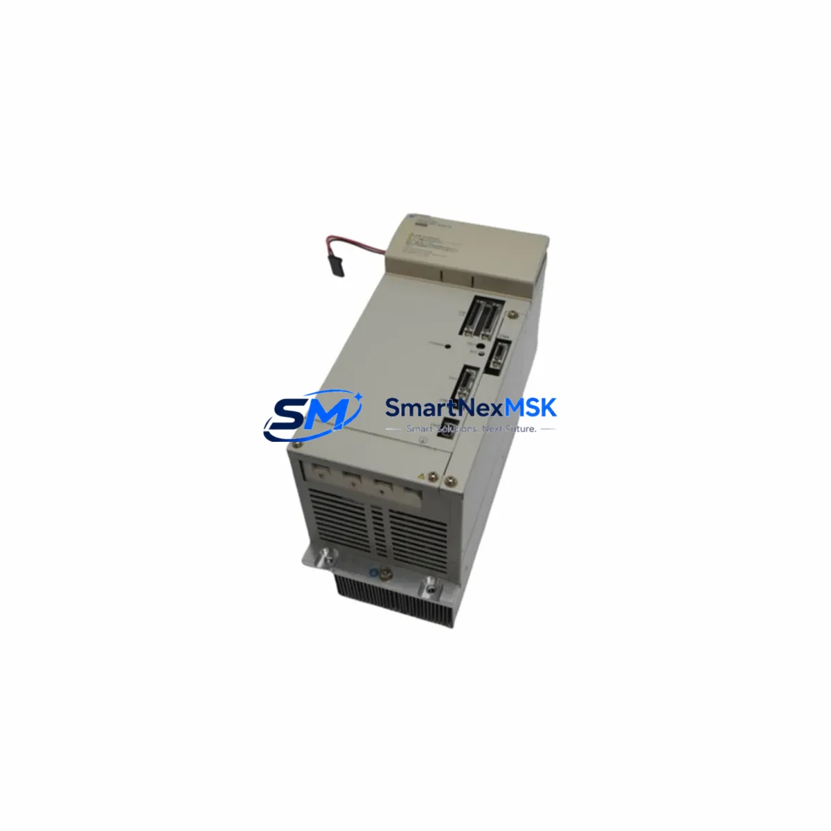
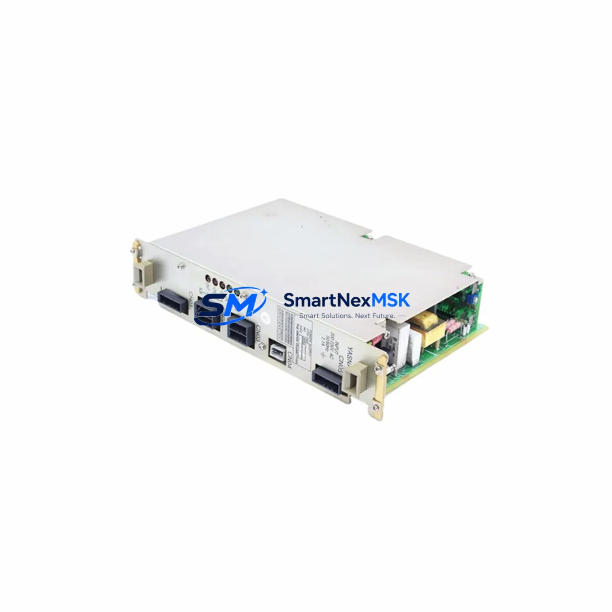
The YASKAWA CPS-150F is a critical power supply module designed for the MP900 and MP2000 series machine controllers — one of YASKAWA’s most widely deployed motion and sequence control platforms in industrial automation environments. When this module fails or degrades, the entire control cabinet loses its regulated DC power backbone, bringing production lines, CNC systems, and coordinated servo drives to an immediate halt. Sourcing a verified, original CPS-150F spare is the fastest path to restoring uptime and protecting downstream equipment from under-voltage or ripple-induced faults.
This listing supplies the CPS-150F as a maintenance-ready, original spare — pre-tested before shipment, packaged for safe transit, and backed by a 12-month warranty. It is stocked to support both planned preventive maintenance schedules and emergency breakdown recovery, with fast dispatch to minimize mean time to repair (MTTR) on your production floor.
Spare Maintenance Table
| Parameter | Specification / Detail |
|---|---|
| Part Number / SKU | CPS-150F |
| Brand | YASKAWA |
| Compatible Series | MP900 Series, MP2000 Series Machine Controllers |
| Module Function | DC Power Supply for Controller Backplane & I/O Modules |
| Rated Output Power | 150 W (nominal) |
| Input Voltage | 100–240 VAC, 50/60 Hz (universal input) |
| Output Voltage | +5 VDC, +24 VDC (multi-rail) |
| Mounting | DIN-rail / backplane slot mount (MP series rack) |
| Operating Temperature | 0°C to +55°C |
| Storage Temperature | -20°C to +85°C |
| Humidity | 10–90% RH, non-condensing |
| Protection Class | IP20 (panel-mount installation) |
| Origin | Japan (Original YASKAWA) |
| Condition | Original, New / Surplus New |
| Pre-shipment Test | Power-on functional test, output voltage verification |
| Warranty | 12 Months from date of shipment |
| Typical Application | CNC machine tools, packaging lines, servo motion systems, process automation |
| Replacement Compatibility | Direct drop-in for CPS-150F in MP900/MP2000 racks; verify slot position and connector keying before installation |
Maintenance Planning for Continuous Operation
For maintenance engineers managing MP900 or MP2000-based control cabinets, the CPS-150F rarely fails in isolation. Power supply degradation typically manifests as intermittent controller resets, erratic servo axis faults, or unexplained communication dropouts — symptoms that can be misdiagnosed as software or network issues. When replacing the CPS-150F, a disciplined site inspection of the surrounding electrical environment is essential to prevent repeat failures and ensure the new module operates within its rated envelope.
Input power quality should be the first checkpoint. Verify that the incoming AC supply to the control cabinet is within the CPS-150F’s rated input range and that the isolation transformer or line filter — such as a YASKAWA SI-series or equivalent EMC filter — is functioning correctly. Transient overvoltages from nearby VFDs or welding equipment are a common root cause of premature power supply failure.
Backplane and rack integrity is the next priority. The MP900/MP2000 backplane distributes the CPS-150F’s DC outputs to all installed modules, including the CPU module (such as the MP2300 or MP2310 controller card), motion module slots, and communication modules like the MECHATROLINK-II or MECHATROLINK-III interface cards. Inspect the backplane connector for oxidation, bent pins, or heat discoloration before seating the replacement module.
I/O and signal modules downstream of the power supply should also be checked. YASKAWA MP-series I/O modules — digital input/output cards and analog signal modules — can draw excessive current if field wiring has developed a partial short or if a connected sensor has failed. Use a clamp meter to verify per-rail current draw is within the CPS-150F’s output ratings before powering up the replacement unit.
24 VDC field power circuits deserve particular attention. Many MP-series installations use the CPS-150F’s 24 VDC rail to power field devices, relay coils, and proximity sensors. A failed relay — for example, a YASKAWA or Omron intermediate relay in the I/O terminal block — can present as a sustained overload on this rail. Inspect relay contacts and coil resistance before commissioning the new power supply.
Communication and HMI continuity should be confirmed after replacement. If the cabinet includes a YASKAWA OP-series operator panel or a third-party HMI connected via RS-232/RS-485 or Ethernet, verify that communication parameters are retained in the CPU’s non-volatile memory and that the HMI re-establishes its connection correctly after power restoration. Similarly, if a PROFIBUS-DP or DeviceNet communication module is installed, confirm that the network address and baud rate settings are intact.
Fuse and circuit protection elements — including the primary AC fuse, DC bus fuses, and any miniature circuit breakers (MCBs) on the 24 VDC distribution rail — should be inspected and replaced if there is any evidence of thermal stress. Fuse holders and terminal blocks (such as Phoenix Contact or Weidmüller DIN-rail terminals) should be checked for loose connections that could cause voltage drop under load.
Maintaining a minimum stock of one CPS-150F per production line, alongside a spare CPU module and at least one I/O expansion card, is a widely adopted strategy in facilities running legacy MP900 systems where YASKAWA has transitioned to newer platforms. This buffer inventory approach ensures that a single component failure does not trigger an extended production outage while a replacement is sourced.
Site Replacement Workflow
Step 1 — Isolate and de-energize. Follow your site’s lockout/tagout (LOTO) procedure. Disconnect the AC input to the control cabinet and verify zero voltage at the CPS-150F input terminals using a calibrated multimeter. Allow capacitors to discharge for a minimum of 60 seconds before handling the module.
Step 2 — Document the existing configuration. Before removing the failed unit, photograph the wiring, note the slot position, and record any DIP switch or jumper settings visible on adjacent modules. For MP2000-series systems, use the YASKAWA MPE720 engineering software to export the current project backup if the CPU is still accessible.
Step 3 — Remove the failed CPS-150F. Release the module locking tabs, disconnect the AC input connector, and slide the module out of the rack. Inspect the vacated slot for debris, corrosion, or damaged backplane contacts.
Step 4 — Install the replacement module. Align the CPS-150F with the rack guides and slide it firmly into the slot until the locking tabs engage. Reconnect the AC input connector and verify that all wiring is secure and correctly torqued to the terminal specifications.
Step 5 — Power-on verification. Restore AC power and observe the CPS-150F status LEDs. Confirm that the POWER indicator illuminates green and that no FAULT or ALARM LEDs are active. Measure the DC output voltages at the backplane test points to verify they are within specification before allowing the CPU to boot.
Step 6 — System functional test. Allow the MP-series controller to complete its self-diagnostic sequence. Verify that all I/O modules, servo axes, and communication links are recognized and operating normally. Run a short production cycle or simulation to confirm full system recovery before returning the line to production.
This workflow is applicable whether you are replacing a failed CPS-150F on an MP900-series rack or upgrading an aging unit as part of a planned preventive maintenance interval. The direct drop-in compatibility of the CPS-150F means no firmware changes or parameter re-entry are required — a significant advantage over cross-brand substitutions that may require engineering rework.
Spare Parts Support FAQ
Q1: Is this CPS-150F compatible with both MP900 and MP2000 series racks?
Yes. The CPS-150F is the standard power supply module for both the MP900 and MP2000 series machine controller families. It is a direct mechanical and electrical fit for any rack slot designated for this module. Always verify the slot label and connector keying on your specific rack revision before installation, as some early MP900 rack variants may have minor mechanical differences.
Q2: What pre-shipment testing is performed on this module?
Each CPS-150F unit undergoes a power-on functional test prior to dispatch. Output voltages on all DC rails are measured and verified against YASKAWA’s published specifications. Units that do not meet specification are quarantined and not shipped. A test record is available upon request for quality-critical applications.
Q3: How should I manage CPS-150F inventory for a multi-line facility?
For facilities operating three or more MP-series controllers, we recommend maintaining a minimum of one CPS-150F per every three controllers as a buffer stock. Given that YASKAWA has phased the MP900 platform toward end-of-life support, lead times for new production units can be extended. Holding verified surplus stock on-site is the most reliable strategy for protecting uptime in legacy system environments.
Q4: What does the 12-month warranty cover?
The 12-month warranty covers manufacturing defects and functional failures under normal operating conditions from the date of shipment. It does not cover damage resulting from incorrect installation, overvoltage events, physical impact, or operation outside the module’s rated environmental parameters. In the event of a warranty claim, we will arrange replacement or repair at no additional cost after fault verification.
© 2026 SMARTNEXMSK. All rights reserved.
Original Source: https://smartnexmsk.com
Contact: sales@smartnexmsk.com | +86 18259474341