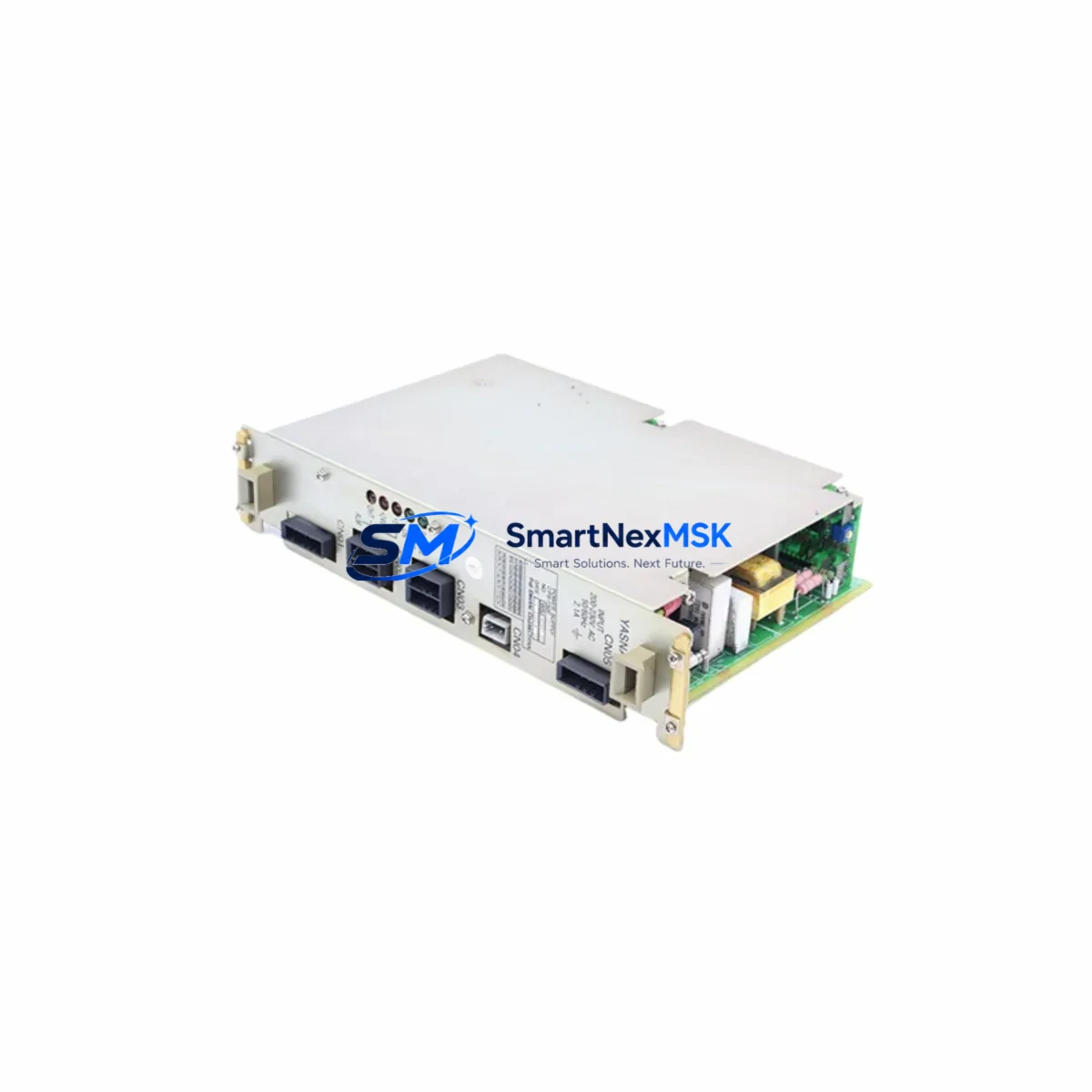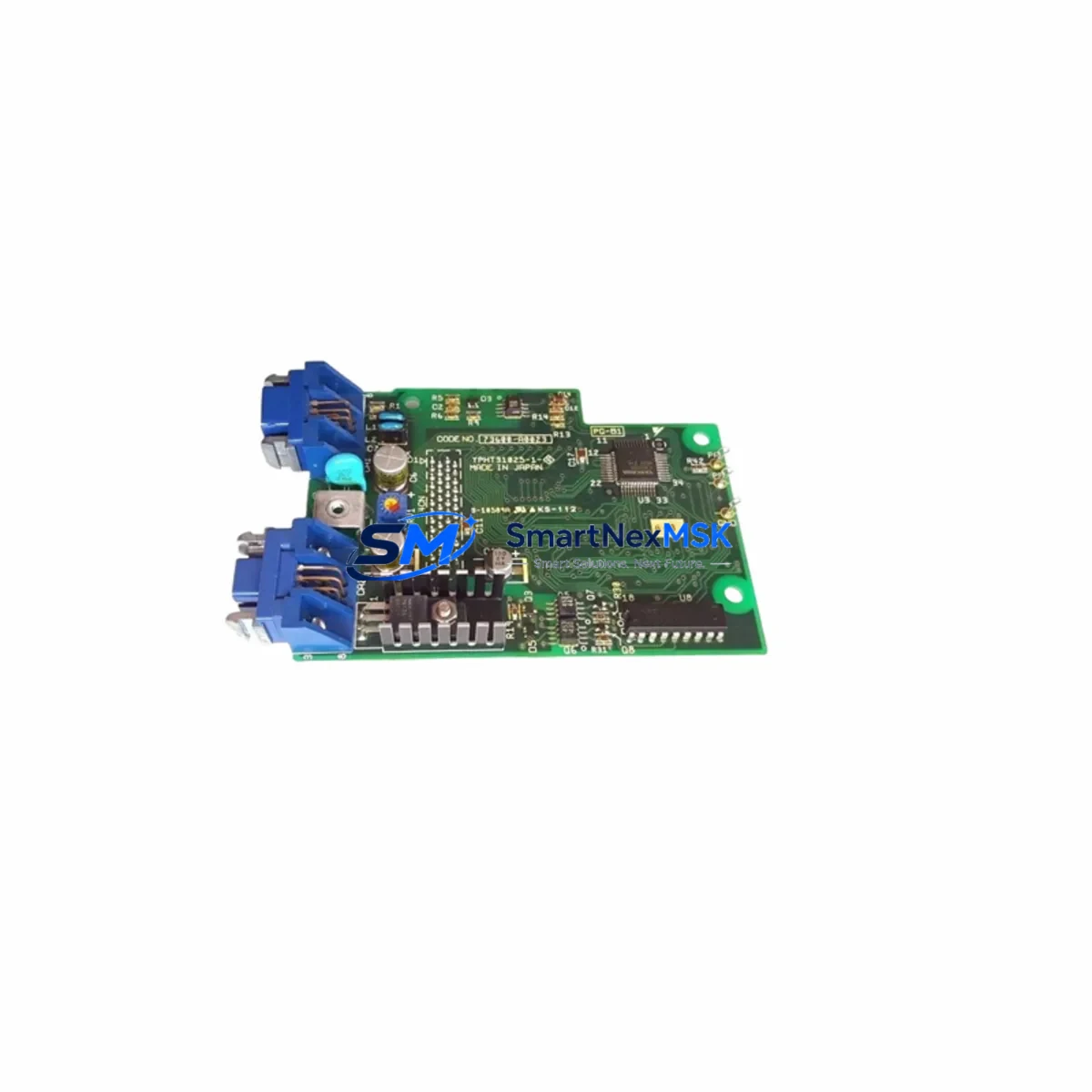
YASKAWA YPHT31033-1-1 Retrofit-Ready Drive Control PCB for YPHT Series Control Systems
The YASKAWA YPHT31033-1-1 (Part No. 73600-A0101) is a Drive Control PCB engineered for direct retrofit and drop-in replacement within YASKAWA YPHT Series variable frequency drive systems. As legacy YPHT Series drives reach end-of-service milestones, this board provides a verified upgrade path that preserves existing wiring harnesses, terminal layouts, and drive logic — minimizing engineering rework and unplanned downtime during modernization projects.
Whether you are managing a planned control cabinet overhaul, responding to an unplanned drive failure, or executing a phased migration from discontinued YASKAWA drive platforms, the YPHT31033-1-1 delivers the electrical and mechanical compatibility required for a smooth transition. Each unit is sourced from verified supply channels, undergoes pre-shipment functional testing, and is backed by a 12-month warranty covering manufacturing defects and operational failures under normal industrial conditions.
Upgrade Compatibility Table
| Parameter | Details |
|---|---|
| SKU / Part Number | YPHT31033-1-1 / 73600-A0101 |
| Brand | YASKAWA |
| Compatible Series | YASKAWA YPHT Series Variable Frequency Drives |
| Board Function | Drive Control PCB (main control logic board) |
| Interface / Backplane | Compatible with YPHT Series drive chassis backplane connectors |
| Terminal Wiring | Matches original YPHT Series terminal block layout; no rewiring required in standard retrofit |
| Communication Compatibility | Supports MEMOBUS/Modbus RTU protocol as per YPHT Series standard configuration |
| Installation Requirement | Direct board swap; verify firmware version and parameter backup before replacement |
| Replacement Recommendation | Suitable for 1:1 replacement of failed or degraded YPHT31033-1-1 boards |
| Commissioning Notes | Restore drive parameters via DriveWizard or keypad after board swap; verify I/O signal mapping |
| Warranty | 12 Months — covers manufacturing defects and operational failure under normal use |
| Pre-Shipment Testing | Functional power-on and signal integrity test performed on every unit |
| Origin | Japan |
Retrofit Planning for Existing Automation Systems
A successful retrofit of the YPHT31033-1-1 begins well before the board is physically installed. Engineers should start by pulling the existing drive’s parameter file using YASKAWA DriveWizard Industrial software, ensuring all motor tuning data, acceleration/deceleration ramps, and fault history are archived. This parameter backup is critical — it allows the replacement board to be initialized with the exact operational profile of the failed unit, avoiding the need for a full motor auto-tune on a live production line.
Before removing the original board, verify the DC bus voltage has fully discharged (typically 5 minutes after power-off) and confirm the control power supply — often a separate 24VDC supply rail within the drive cabinet — is isolated. In multi-drive cabinets, the YASKAWA CIMR-series power supply modules feeding the control logic must be checked for output stability, as a degraded control power rail is a common root cause of repeated PCB failures.
During the physical swap, inspect the backplane connector on the drive chassis for bent pins or corrosion. In older YPHT Series installations, the backplane may also interface with a YASKAWA SI-series communication option card (such as the SI-EP3 for PROFINET or SI-EM3 for EtherNet/IP). These option cards mount independently and are typically retained during a control board replacement — confirm the card’s firmware is compatible with the replacement board revision before powering up.
For systems where the YPHT drive interfaces with a YASKAWA MP3000 Series machine controller or a third-party PLC via MEMOBUS/Modbus RTU, verify the communication node address and baud rate settings are correctly restored after the board swap. In distributed I/O architectures, the drive may also receive speed reference and run/stop commands from a YASKAWA VS-616G5 or similar upstream controller — confirm the analog input scaling and digital input logic have not shifted after the replacement.
In control cabinets where the YPHT drive operates alongside YASKAWA JZRCR-series servo amplifiers or SGDV-series Sigma-V servo drives, pay attention to the common DC bus configuration if applicable. A new control board may reset the drive’s DC bus sharing parameters to factory defaults, which can cause instability in regenerative braking applications. Always verify these parameters against the original backup before releasing the system to production.
For HMI integration, if the drive’s status and fault data are displayed on a YASKAWA GP-Pro EX panel or a third-party SCADA system via OPC-UA or Modbus TCP gateway, confirm that the register map used by the HMI project matches the parameter addresses of the replacement board. Minor firmware revisions between board generations can occasionally shift register offsets for fault codes and output frequency monitoring.
Downtime Control During System Migration
Minimizing production downtime during a drive control board replacement requires a structured pre-maintenance protocol. The most effective approach is to prepare a complete commissioning kit before the maintenance window opens: this includes the replacement YPHT31033-1-1 board, a laptop with DriveWizard Industrial pre-loaded with the parameter backup file, a calibrated multimeter for DC bus discharge verification, and the drive’s wiring diagram specific to the installation.
For critical production lines where even a 30-minute outage carries significant cost, consider staging a fully pre-configured spare drive — with the YPHT31033-1-1 already installed and parameters loaded — as a hot-swap unit. This approach reduces the in-field replacement time to a cable transfer and power-on verification, typically achievable within 15–20 minutes. The original drive chassis can then be returned to the workshop for a more thorough inspection and board-level repair assessment.
During the replacement, maintain the original program logic in the upstream PLC or machine controller without modification. The drive’s control board replacement should be transparent to the PLC — the drive will respond to the same run/stop commands, speed references, and fault reset signals as before, provided parameters are correctly restored. If the system uses a YASKAWA MP2000 or MP3000 Series controller with a motion program referencing the drive’s status words, perform a dry-run simulation before re-engaging the load to confirm all interlocks and safety logic respond correctly.
After power-up, monitor the drive’s output current, output frequency, and DC bus voltage on the keypad or via DriveWizard for the first 10–15 minutes of operation under load. Any deviation from the pre-replacement baseline — particularly in current draw or thermal performance — should be investigated before the system is returned to full production speed. Document the replacement date, board serial number, and post-commissioning parameter file in the equipment maintenance log for future reference.
Retrofit Support FAQ
Q1: Is the YPHT31033-1-1 (73600-A0101) a direct 1:1 replacement for the original board in my YPHT Series drive?
Yes. The YPHT31033-1-1 with part number 73600-A0101 is designed as a direct replacement for the same board designation in YPHT Series drives. The connector layout, mounting points, and electrical interface are identical to the original. We recommend backing up your drive parameters before replacement and restoring them after installation to ensure the drive operates with your existing motor tuning and application settings.
Q2: What commissioning steps are required after installing the replacement board?
After physical installation, restore the parameter backup using YASKAWA DriveWizard Industrial or the drive keypad. Verify the motor nameplate data (rated voltage, current, frequency, speed) matches the stored parameters. Perform a no-load test run to confirm output frequency and rotation direction before reconnecting the mechanical load. If the drive communicates with a PLC or HMI, confirm the communication link is re-established and all status registers are reading correctly.
Q3: Does the replacement board affect my existing wiring and terminal connections?
No rewiring is required for a standard board swap. The YPHT31033-1-1 maintains the same terminal block layout and signal assignments as the original board. However, if your installation includes a YASKAWA SI-series communication option card, confirm the card is reseated securely after the board replacement, as the option card connector can loosen during the swap process.
Q4: What does the 12-month warranty cover, and how is it handled?
The 12-month warranty covers manufacturing defects and operational failures under normal industrial operating conditions. If the board fails within the warranty period, contact sales@smartnexmsk.com with your order details and a description of the fault. We will arrange a replacement or repair at no additional cost. Warranty does not cover damage caused by incorrect installation, overvoltage events, or physical impact.
© 2026 SMARTNEXMSK. All rights reserved.
Original Source: https://smartnexmsk.com
Contact: sales@smartnexmsk.com | +86 18259474341