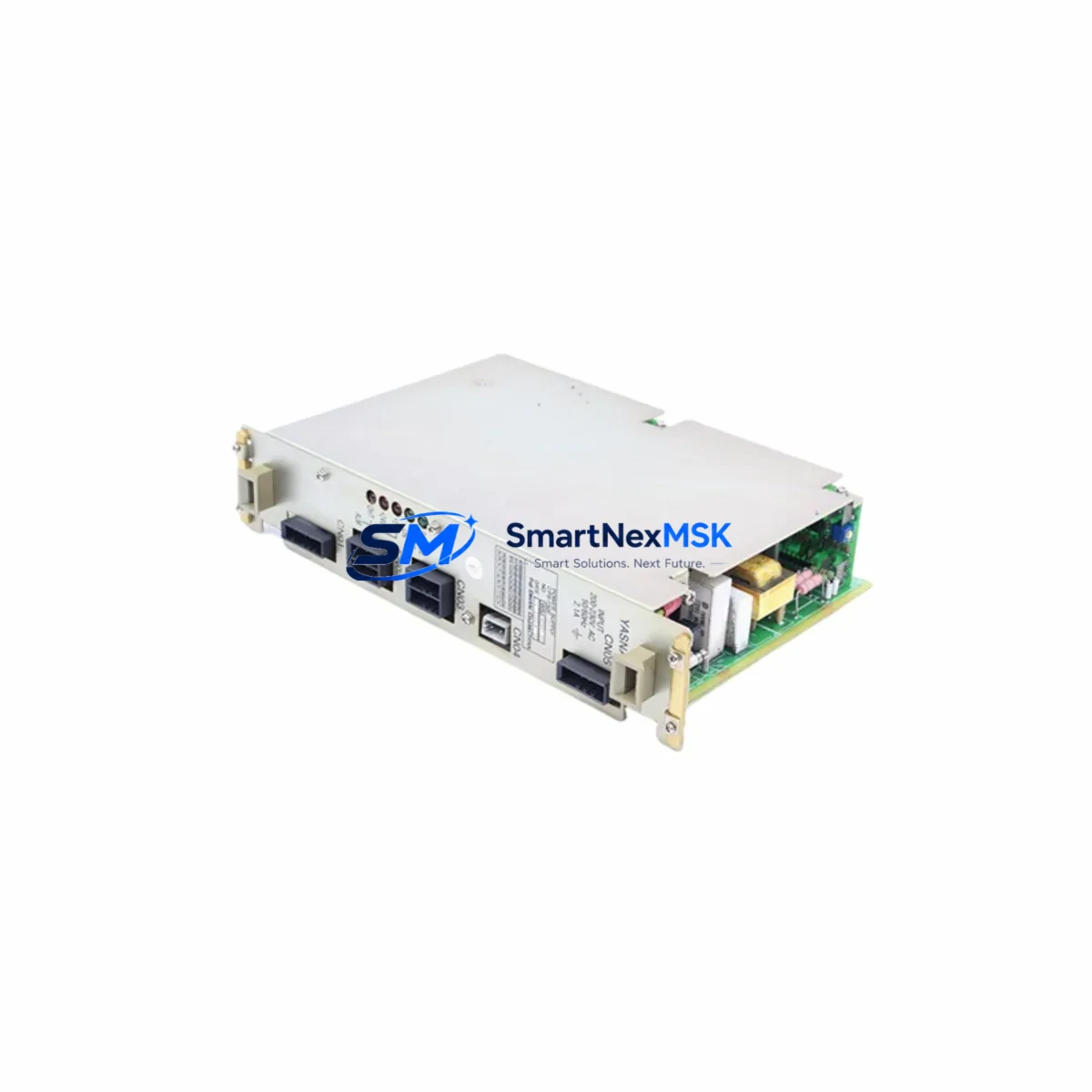
YASKAWA JANCD-XCP01C-1 Retrofit CPU for XRC Control Systems: Compatible Upgrade for Legacy Robot Controllers
The YASKAWA JANCD-XCP01C-1 is a central processing unit board designed for the YASKAWA XRC series robot controller — one of the most widely deployed robot control platforms in automotive, metal fabrication, and general industrial automation environments. As the XRC platform approaches end-of-life support cycles, procurement teams and maintenance engineers increasingly rely on verified retrofit-ready replacements to extend the operational life of existing robot cells without committing to a full controller replacement. The JANCD-XCP01C-1 serves precisely this role: a functionally equivalent, drop-in compatible CPU board that restores full controller operation with minimal downtime and no requirement to reprogram the robot from scratch.
This board interfaces directly with the XRC controller backplane and communicates with peripheral boards including the JANCD-XIF01 interface board, the JANCD-XIO01 I/O expansion board, and the JANCD-XMS01 memory storage board. When replacing a failed CPU board, engineers must verify that the firmware revision on the JANCD-XCP01C-1 matches or is compatible with the existing JANCD-XMS01 memory board, as job data, system parameters, and tool calibration files are stored on the memory module rather than the CPU itself. This architecture means that in most retrofit scenarios, the robot’s existing program logic, coordinate systems, and I/O assignments are preserved after the CPU swap — a critical advantage for minimizing production downtime.
Upgrade Compatibility Table
| Parameter | Detail |
|---|---|
| Compatible Controller | YASKAWA XRC Series Robot Controller |
| Replaces / Supersedes | JANCD-XCP01B, JANCD-XCP01 (earlier revisions) |
| Backplane Interface | XRC standard backplane slot — direct plug-in replacement |
| Communication Compatibility | DeviceNet, Ethernet (optional), RS-232C serial; compatible with JANCD-XEW01 Ethernet board |
| Memory Board Dependency | Works with JANCD-XMS01; firmware version alignment required |
| I/O Expansion | Compatible with JANCD-XIO01 I/O board and JZNC-XIU01 I/O unit |
| Teach Pendant | Compatible with JANCD-XCP01C-1 driven XRC pendant (JZRCR-XPP01B-1) |
| Installation Requirement | ESD precautions; power-off before board swap; re-initialize system clock after replacement |
| Commissioning Note | Verify alarm history clear, I/O check, and axis calibration after installation |
| Warranty | 12-Month Warranty — covers manufacturing defects and functional failure under normal operating conditions |
Retrofit Planning for Existing Automation Systems
Successful integration of the JANCD-XCP01C-1 into an existing XRC-based robot cell requires a structured pre-replacement audit. Before powering down the controller, maintenance teams should back up all job files, system parameters, and I/O assignments using the JZRCR-XPP01B-1 teach pendant or via the RS-232C port to a connected PC running YASKAWA’s MotoSim or a compatible backup utility. This backup is stored on the JANCD-XMS01 memory board, but a secondary PC-side copy is strongly recommended as a recovery safeguard.
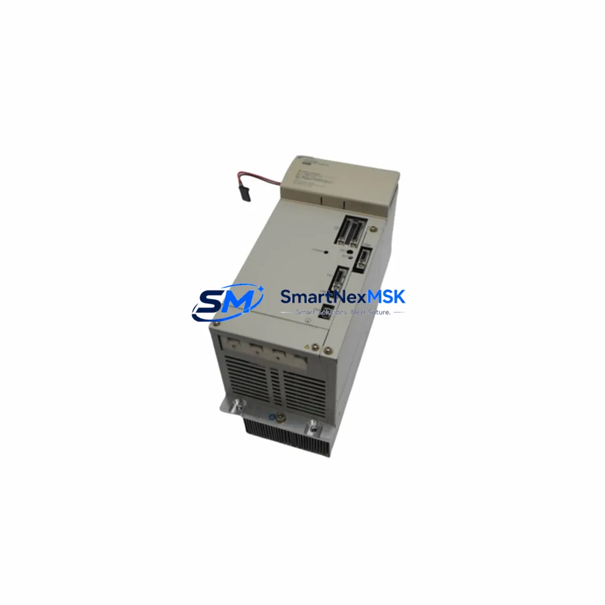
The XRC controller cabinet typically houses the CPU board alongside the JANCD-XIF01 interface board, which manages communication between the CPU and the robot’s servo amplifier units. When the JANCD-XCP01C-1 is installed, the interface board does not require replacement unless it has independently failed — a common diagnostic mistake that leads to unnecessary parts expenditure. Engineers should confirm that the JANCD-XIF01 is returning normal status LEDs before attributing a fault to the CPU board alone.
For facilities running multiple XRC controllers networked via DeviceNet or a JZNC-XIU01 I/O unit, the replacement CPU must be configured with the correct node address and baud rate settings to rejoin the network without disrupting adjacent controllers. In multi-robot cells where a YASKAWA NX100 or DX100 controller operates alongside legacy XRC units, the network topology should be documented before any board-level intervention to avoid address conflicts during restart.
Power supply integrity is a frequently overlooked factor in XRC CPU board failures. Before installing the JANCD-XCP01C-1, verify that the controller’s internal power supply unit — typically a JUSP-OP05AAA-1 or equivalent XRC power board — is delivering stable 5V and 24V DC rails. A degraded power supply can damage a new CPU board within hours of installation. Measuring rail voltages at the backplane connector before board insertion is a mandatory step in any professional retrofit procedure.
If the retrofit is part of a broader control cabinet upgrade that includes replacing the JZRCR-XPP01B-1 teach pendant or adding the JANCD-XEW01 Ethernet communication board for remote monitoring, these components should be staged and tested in sequence rather than simultaneously, allowing each subsystem to be validated independently before the full system is brought back online.
Downtime Control During System Migration
Minimizing unplanned downtime during a CPU board replacement on an XRC robot controller depends on preparation, parts availability, and a disciplined commissioning sequence. The JANCD-XCP01C-1 is shipped pre-tested and ready for installation, which eliminates the bench-testing phase that is otherwise required for untested surplus boards. With a verified replacement board on hand, the physical swap can typically be completed within 30 to 60 minutes by a qualified automation technician.
The most time-sensitive step is the post-installation system verification. After the JANCD-XCP01C-1 is seated and the controller is powered on, the system will perform a self-diagnostic sequence. Engineers should monitor the alarm display on the JZRCR-XPP01B-1 teach pendant for any residual fault codes related to the memory board, servo amplifier communication, or I/O initialization. Clearing these alarms in the correct sequence — CPU alarms first, then communication alarms, then I/O alarms — prevents cascading fault conditions that can extend the restart process unnecessarily.
For production environments where even a 30-minute outage carries significant cost, a cold-standby strategy is recommended: maintaining one pre-configured JANCD-XCP01C-1 board in inventory, paired with a current backup of the robot’s job files and system parameters. This approach reduces mean time to repair (MTTR) to under one hour for any XRC CPU failure scenario, regardless of the complexity of the robot program or the number of I/O points in use.
Where the XRC controller is integrated with a PLC-based safety circuit — for example, a SIEMENS S7-300 or OMRON CJ2M managing the robot’s safety gate and emergency stop inputs — the PLC program logic does not need to be modified during a CPU board replacement, provided the XRC’s I/O assignments and safety relay wiring remain unchanged. This cross-platform compatibility is a key advantage of board-level replacement over full controller migration.
Retrofit Support FAQ
Q1: Is the JANCD-XCP01C-1 a direct drop-in replacement for the JANCD-XCP01B?
In most XRC installations, yes. The JANCD-XCP01C-1 is the current revision of the XRC CPU board and is backward compatible with the JANCD-XCP01B and earlier JANCD-XCP01 variants. However, firmware version alignment with the JANCD-XMS01 memory board should be confirmed before installation. If the memory board carries an older firmware version, a firmware update may be required — contact our technical team for guidance specific to your controller’s serial number and software version.
Q2: Will my existing robot programs and calibration data be preserved after the CPU board swap?
Yes, provided the JANCD-XMS01 memory board is intact and undamaged. All job files, system parameters, tool data, and coordinate system definitions are stored on the memory board, not the CPU board. The JANCD-XCP01C-1 reads this data on startup. As a precaution, always perform a full system backup via the teach pendant or RS-232C interface before beginning any board-level replacement.
Q3: What wiring or terminal changes are required when installing the JANCD-XCP01C-1?
No external wiring changes are required for a like-for-like CPU board replacement. The JANCD-XCP01C-1 connects exclusively via the XRC backplane connector — there are no field-wired terminals on the CPU board itself. All I/O wiring, safety circuit connections, and communication cables remain connected to their respective boards (JANCD-XIO01, JANCD-XIF01, JANCD-XEW01) and do not need to be disturbed during the CPU swap.
Q4: What does the 12-month warranty cover, and how is it processed?
The 12-month warranty covers manufacturing defects and functional failure under normal operating conditions, including board-level component failure not caused by external damage, incorrect installation, or power supply anomalies. Each JANCD-XCP01C-1 unit is functionally tested prior to shipment. In the event of a warranty claim, contact sales@smartnexmsk.com with your order reference and a description of the fault. Replacement or repair will be arranged promptly, with return shipping coordinated by our team.
© 2026 SMARTNEXMSK. All rights reserved.
Original Source: https://smartnexmsk.com
Contact: sales@smartnexmsk.com | +86 18259474341