Yaskawa JZNC-YPS21-E Maintenance-Ready Spare for DX Series Automation
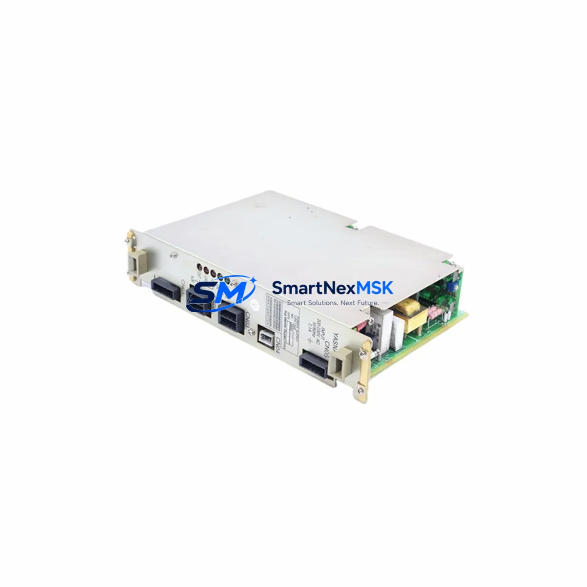
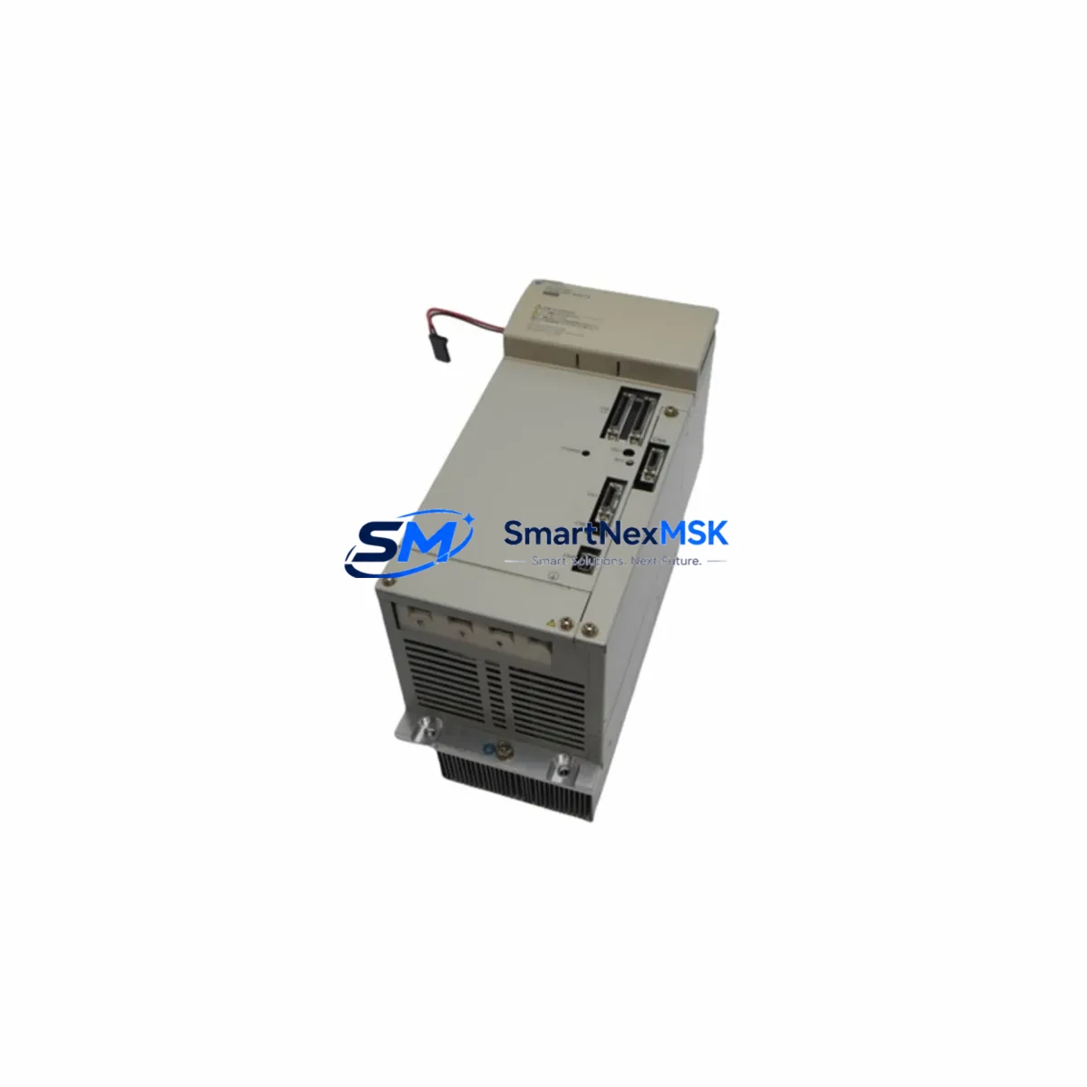
The Yaskawa JZNC-YPS21-E (cross-compatible with JZNC-YPS01-E) is the dedicated power supply unit (PSU) for Yaskawa DX100 and DX200 robot controllers — two of the most widely deployed motion-control platforms in automotive, metal fabrication, electronics assembly, and general industrial automation. When this PSU fails or degrades, the entire robot cell goes offline. Sourcing a verified, tested replacement quickly is the single most effective action a maintenance team can take to restore production and minimize unplanned downtime costs.
At SMARTNEXMSK, every JZNC-YPS21-E unit is sourced from authorized supply channels, subjected to pre-shipment electrical verification, and backed by a 12-month warranty. Stock is maintained on-hand to support same-day or next-business-day dispatch, making this listing a reliable anchor for your DX-series spare parts program.
Spare Maintenance Table
| Parameter | Specification / Detail |
|---|---|
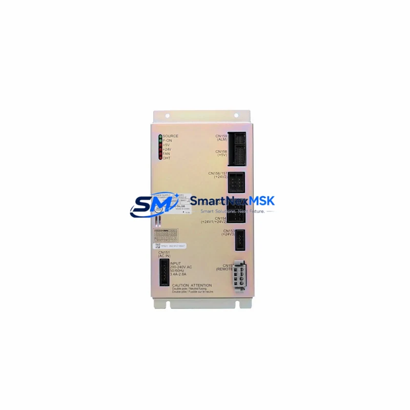
| Part Number | JZNC-YPS21-E / JZNC-YPS01-E (cross-compatible) |
| Brand | Yaskawa Electric Corporation |
| Series Compatibility | DX100, DX200 Robot Controllers |
| Function | Internal Power Supply Unit — provides regulated DC rails to controller backplane, CPU board, and I/O modules |
| Input Voltage | AC 200–240 V, 50/60 Hz (single-phase) |
| Output Rails | +5 VDC, +24 VDC (logic and I/O supply) |
| Mounting | DIN-rail / panel-mount inside DX controller cabinet |
| Connector Interface | OEM Yaskawa multi-pin harness — direct plug-in replacement |
| Country of Origin | Japan |
| Condition | Original / New-surplus / Tested serviceable (stated per unit) |
| Pre-shipment Test | Output voltage verification, load regulation check, insulation resistance |
| Application Environment | Industrial robot controller cabinet; IP54 enclosure recommended |
| Operating Temperature | 0 °C to +55 °C |
| Storage Temperature | −20 °C to +70 °C |
| Warranty | 12 months from date of shipment |
| Lead Time | In-stock — same-day / next-business-day dispatch available |
| Packaging | Anti-static bag, foam-lined carton, shock-indicator label |
Maintenance Planning for Continuous Operation
A PSU failure in a DX100 or DX200 controller rarely occurs in isolation. Voltage ripple, capacitor aging, and thermal stress affect multiple components simultaneously. When replacing the JZNC-YPS21-E, a disciplined maintenance engineer will use the opportunity to inspect and — where service intervals dictate — proactively replace adjacent components to prevent a second unplanned outage within weeks.
Begin with the JZNC-YRK21-1E robot control board (CPU board): it is the primary consumer of the PSU’s +5 V rail, and a marginal PSU can cause intermittent CPU resets that are misdiagnosed as software faults. Verify the CPU board’s capacitors and confirm alarm history for A.8A0 or A.8A1 power-fault codes before closing the cabinet.
Next, inspect the JZNC-YIU21-E I/O unit and its associated JZNC-YIU22-E expansion I/O board. These modules draw from the +24 V logic rail; a failing PSU often causes intermittent digital input dropouts that manifest as random E-stop faults or teach-pendant communication errors. Confirm all I/O connector latches are seated and check for corrosion on the 50-pin ribbon connectors.
The JZNC-YSF21-E safety board must also be verified. This module monitors dual-channel E-stop, fence interlock, and servo-enable signals. If the +24 V supply was unstable prior to PSU failure, the safety board’s relay contacts may have experienced abnormal cycling — inspect contact wear and test the dual-channel response time per the DX100/DX200 maintenance manual.
For systems with servo amplifier integration, check the CACR-SR servo amplifier power section and its associated JZRCR-YPU21-1 power unit. Undervoltage events from a degraded PSU can trigger overcurrent protection in the servo amplifier, leaving latent fault codes even after the PSU is replaced. Clear all servo amplifier fault logs and perform a controlled jog cycle before returning the cell to production.
Do not overlook the teach pendant cable (JZRCR-YPP21-1) and the DX-series backplane bus board. Voltage transients during PSU failure can damage the pendant interface circuit and corrupt backplane communication. A quick pendant self-test and backplane continuity check takes under ten minutes and can prevent a costly second service call.
Finally, review the cabinet’s 24 VDC terminal block distribution rail, circuit breakers, and EMC line filter. Loose terminal connections and degraded filter capacitors are common root causes of PSU stress. Torque all terminals to specification and replace any discolored or heat-damaged components before commissioning the repaired controller.
Site Replacement Workflow
Step 1 — Isolate and de-energize. Follow your site LOTO procedure. Confirm zero-energy state on the DX controller cabinet before opening the door. Allow 5 minutes for internal capacitors to discharge after main power is removed.
Step 2 — Document and photograph. Photograph all cable harness routing and connector positions on the existing JZNC-YPS21-E before disconnection. The multi-pin harness connectors are keyed but documenting the as-found state eliminates reassembly errors.
Step 3 — Remove the failed unit. Release the DIN-rail locking tab or unscrew the panel-mount fasteners (M4 × 4 positions). Disconnect the AC input connector and all DC output harnesses. Note any discoloration, burn marks, or swollen capacitors on the removed unit — these indicate root-cause conditions that must be addressed before the replacement is installed.
Step 4 — Install the replacement JZNC-YPS21-E. Seat the unit on the DIN rail or panel mount. Reconnect all harnesses in reverse order of removal. Verify connector latch engagement by gentle pull-test on each connector body.
Step 5 — Power-up and verify. Apply main power. Observe the controller boot sequence. Confirm no alarm codes on the teach pendant. Measure output voltages at the test points specified in the DX100/DX200 maintenance manual (+5 V ±2%, +24 V ±5%). Perform a full I/O check and a controlled jog cycle before releasing the cell to production.
Step 6 — Update maintenance records. Log the replacement date, unit serial number, and pre-shipment test certificate number in your CMMS. Schedule the next PSU inspection at 20,000 operating hours or 3 years, whichever comes first.
Spare Parts Support FAQ
Q1: Is the JZNC-YPS21-E a direct drop-in replacement for the JZNC-YPS01-E?
Yes. The JZNC-YPS21-E is the current-production successor to the JZNC-YPS01-E and is mechanically and electrically interchangeable in all DX100 and DX200 controller variants. No firmware or parameter changes are required after installation.
Q2: What pre-shipment testing is performed on each unit?
Every unit undergoes output voltage verification under rated load, load regulation measurement across the full output current range, and insulation resistance testing between input and output rails. A test certificate is included with each shipment. Units that do not meet Yaskawa’s published specifications are not dispatched.
Q3: How should I manage JZNC-YPS21-E inventory for a multi-robot facility?
Industry best practice for facilities operating 10 or more DX-series robots is to maintain a minimum of one PSU per 10 robots as on-site buffer stock, with a reorder point triggered when buffer stock falls to 50%. For critical 24/7 production lines, a 1:5 ratio is recommended. SMARTNEXMSK supports blanket-order arrangements and scheduled replenishment to help procurement teams maintain optimal stock levels without excessive capital tie-up.
Q4: What is covered under the 12-month warranty?
The 12-month warranty covers manufacturing defects, component failure under normal operating conditions, and any deviation from the published electrical specifications confirmed by our pre-shipment test data. It does not cover damage resulting from incorrect installation, overvoltage events, physical impact, or operation outside the specified environmental range. Warranty claims are processed within 5 business days of receipt of the returned unit.
© 2026 SMARTNEXMSK. All rights reserved.
Original Source: https://smartnexmsk.com
Contact: sales@smartnexmsk.com | +86 18259474341