Yaskawa JZRCR-APP01-1 Maintenance-Ready Spare YRC1000 Automation
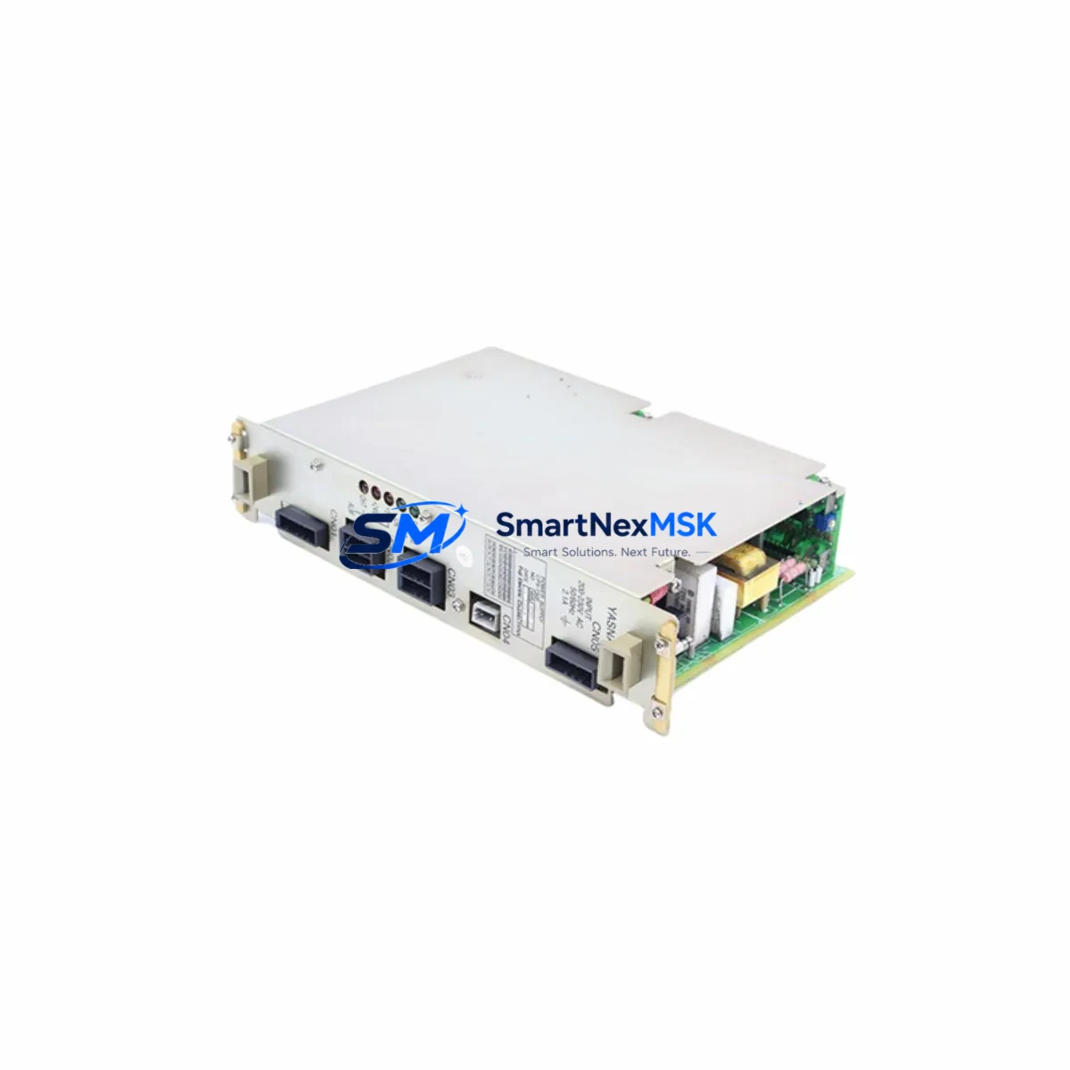
The Yaskawa JZRCR-APP01-1 is the central CPU board of the YRC1000 robot controller — the core processing unit responsible for motion control, I/O coordination, safety logic, and real-time communication across the entire robotic system. When this board fails or degrades, the robot arm halts completely, triggering unplanned downtime that can cascade across production lines, assembly cells, and automated welding or handling stations. Sourcing a verified original replacement quickly is the single most critical step in restoring operations.
At SMARTNEXMSK, every JZRCR-APP01-1 unit is sourced from authorized supply channels, inspected against Yaskawa’s original specifications, and tested under load before shipment. Our industrial spare parts support team maintains long-term stock of YRC1000 series components to serve maintenance engineers and procurement teams who cannot afford extended lead times from OEM channels. Whether you are managing a planned overhaul, responding to an emergency fault, or building a strategic spare parts buffer, this CPU board is available for immediate dispatch with full documentation.
Spare Maintenance Table
| Part Number | JZRCR-APP01-1 |
| Brand | Yaskawa Electric Corporation |
| Compatible Controller | YRC1000 Robot Controller |
| Component Function | Main CPU Processing Board — motion control, I/O management, safety logic |
| Board Type | Embedded Industrial CPU PCB |
| Origin | Japan |
| Operating Voltage | DC 5V / 24V (supplied via YRC1000 internal backplane) |
| Communication Interfaces | EtherNet/IP, DeviceNet, PROFIBUS (via optional communication boards) |
| Installation Method | Direct board replacement within YRC1000 controller cabinet |
| Compatibility | Yaskawa YRC1000 series; verify firmware revision before installation |
| Application Environment | Industrial robot cells, welding stations, assembly lines, material handling |
| Condition | Original, new or refurbished-to-spec; tested before shipment |
| Warranty | 12 Months from date of shipment |
| Lead Time | In stock — same-day or next-business-day dispatch available |
Maintenance Planning for Continuous Operation
Replacing the JZRCR-APP01-1 CPU board is rarely an isolated task. Experienced maintenance engineers know that a CPU board failure in the YRC1000 controller is often accompanied by — or can cause — secondary faults in adjacent components. A thorough site inspection and controlled replacement procedure should include the following checks:
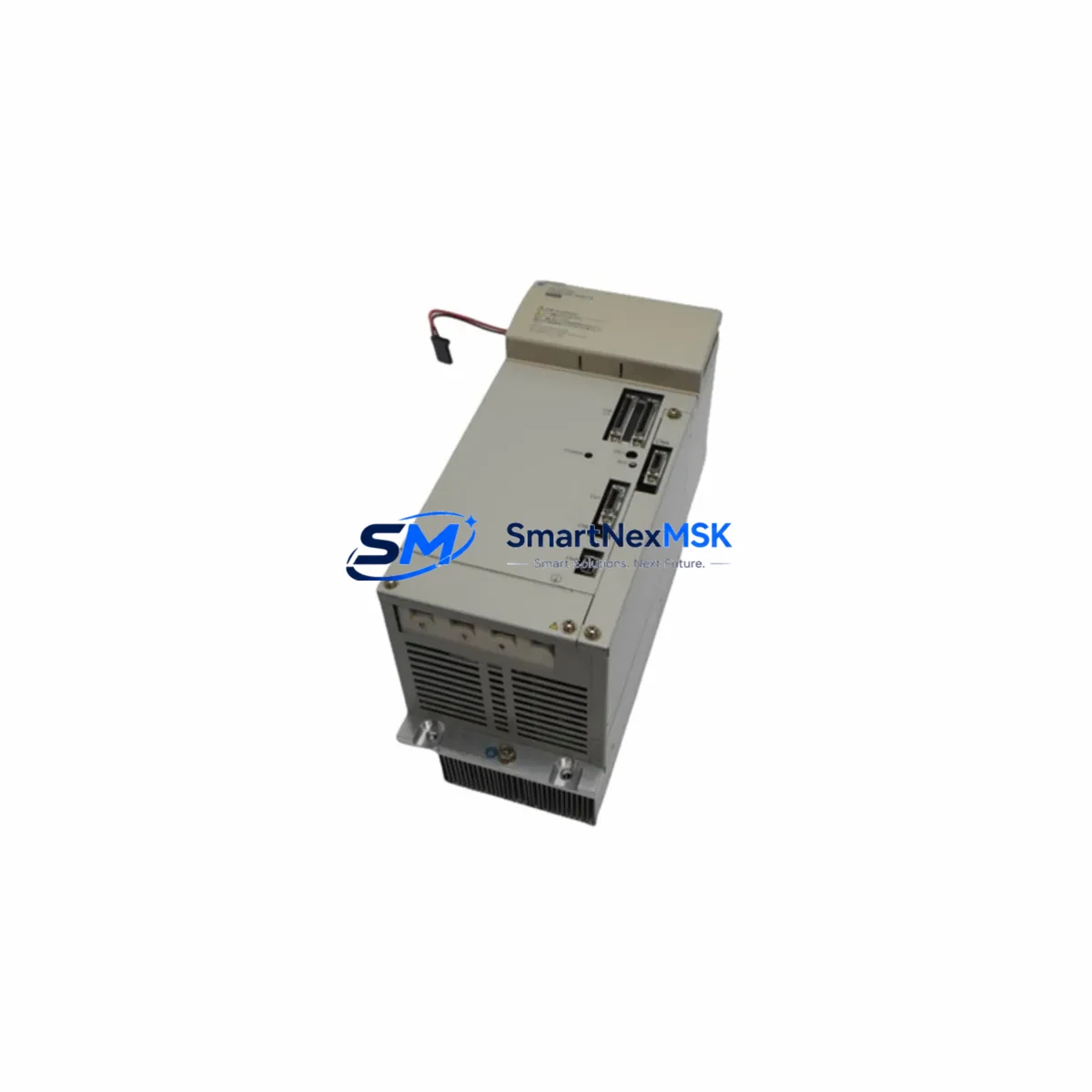
Begin with the YRC1000 power supply unit (typically the JZNC-YRK01-1E or equivalent). A degraded or unstable DC power rail is one of the leading causes of CPU board corruption and premature failure. Verify output voltages under load before installing the replacement board. Next, inspect the backplane board that connects the CPU to I/O and communication modules — damaged connector pins or oxidized contacts can cause intermittent faults that mimic CPU failure.
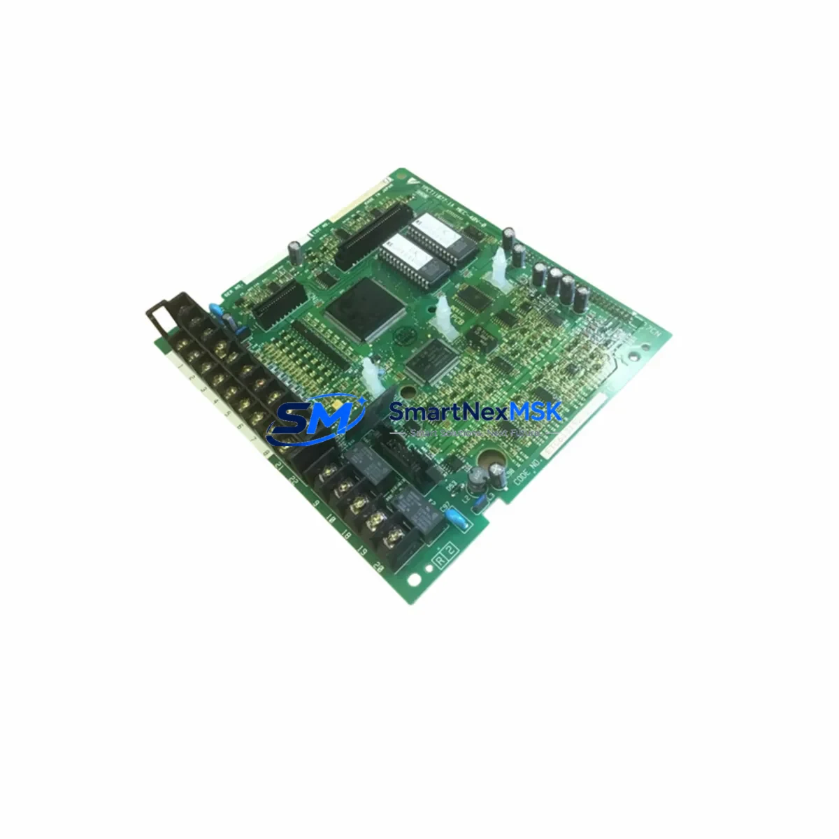
Check all I/O expansion boards installed in the YRC1000 rack. Boards such as the JANCD-YIO21-E handle digital input and output signals to end-effectors, safety gates, and peripheral equipment. A shorted I/O channel can place excessive load on the CPU board’s signal bus. Similarly, inspect the servo amplifier interface board (JANCD-YSF21-E or similar) for fault codes that may have been masked by the CPU failure.
For systems using fieldbus communication, verify the PROFIBUS or EtherNet/IP communication board (such as JANCD-YCP21-E) is seated correctly and free of firmware conflicts. Communication board mismatches after a CPU replacement are a common source of post-maintenance faults. If the robot is integrated with a Yaskawa DX200 or FS100 pendant (HMI) in a multi-robot cell, confirm that the teach pendant cable and connector are undamaged, as pendant communication errors can prevent the new CPU from initializing correctly.
Do not overlook safety relay modules and emergency stop circuits within the control cabinet. These components interact directly with the CPU’s safety logic and must be verified functional before returning the robot to automatic mode. Inspect terminal blocks and wiring harnesses for signs of heat damage, loose crimps, or insulation breakdown — particularly on 24VDC control wiring. Finally, check battery backup units for the CPU’s memory retention; a depleted battery will cause program and parameter loss on first power-up after board replacement, requiring a full system restore from backup.
Maintaining a structured spare parts kit for the YRC1000 — including the JZRCR-APP01-1 CPU board, at least one power supply unit, a set of I/O boards, and communication modules — is the most effective strategy for minimizing mean time to repair (MTTR) in high-utilization robot cells.
Site Replacement Workflow
Step 1 — Fault Isolation: Use the YRC1000 teach pendant to retrieve active alarm codes. CPU-related faults typically appear in the 4000–4999 alarm range. Document all active and historical alarms before powering down.
Step 2 — Safe Shutdown: Place the robot in maintenance mode, engage the mechanical brake, and follow Yaskawa’s lockout/tagout procedure for the YRC1000 controller cabinet. Discharge capacitors per the service manual before opening the cabinet.
Step 3 — Board Removal: Photograph the existing board orientation, connector positions, and any jumper or DIP switch settings before removal. The JZRCR-APP01-1 is secured by mounting screws and edge connectors — handle with ESD precautions throughout.
Step 4 — Firmware and Parameter Verification: Confirm that the replacement JZRCR-APP01-1 carries the same firmware revision as the original, or that a firmware update procedure is available. Load system parameters and robot programs from backup media before powering up.
Step 5 — Power-Up and Functional Test: Restore power in stages. Verify DC rail voltages, check for alarm-free initialization, and run a slow-speed functional test of all robot axes before returning to production speed. Confirm I/O, safety circuits, and communication links are all operational.
This workflow minimizes re-work risk and ensures the replacement board is validated in the actual operating environment before full production resumes.
Spare Parts Support FAQ
Q: How long is the warranty on the JZRCR-APP01-1?
A: All units supplied by SMARTNEXMSK carry a 12-month warranty from the date of shipment. This covers manufacturing defects and functional failures under normal operating conditions. Each board is tested before dispatch to confirm baseline functionality.
Q: Can this CPU board replace older YRC1000 revisions?
A: The JZRCR-APP01-1 is designed for the YRC1000 platform. Compatibility across hardware revisions depends on firmware version and system configuration. We recommend providing your controller’s serial number and current firmware revision when ordering so our technical team can confirm direct compatibility before shipment.
Q: What is your typical lead time and how is the board tested before shipment?
A: In-stock units are dispatched same-day or next business day. Each JZRCR-APP01-1 undergoes visual inspection, connector integrity check, and functional power-on testing prior to packaging. Units are shipped in anti-static packaging with full documentation.
Q: Do you support long-term or repeat supply for maintenance contracts?
A: Yes. SMARTNEXMSK maintains ongoing stock of YRC1000 series spare parts to support maintenance contracts, annual inspection programs, and strategic spare parts buffer programs. Contact our team to discuss volume pricing, reserved stock arrangements, and scheduled delivery options for multi-site operations.
© 2026 SMARTNEXMSK. All rights reserved.
Original Source: https://smartnexmsk.com
Contact: sales@smartnexmsk.com | +86 18259474341