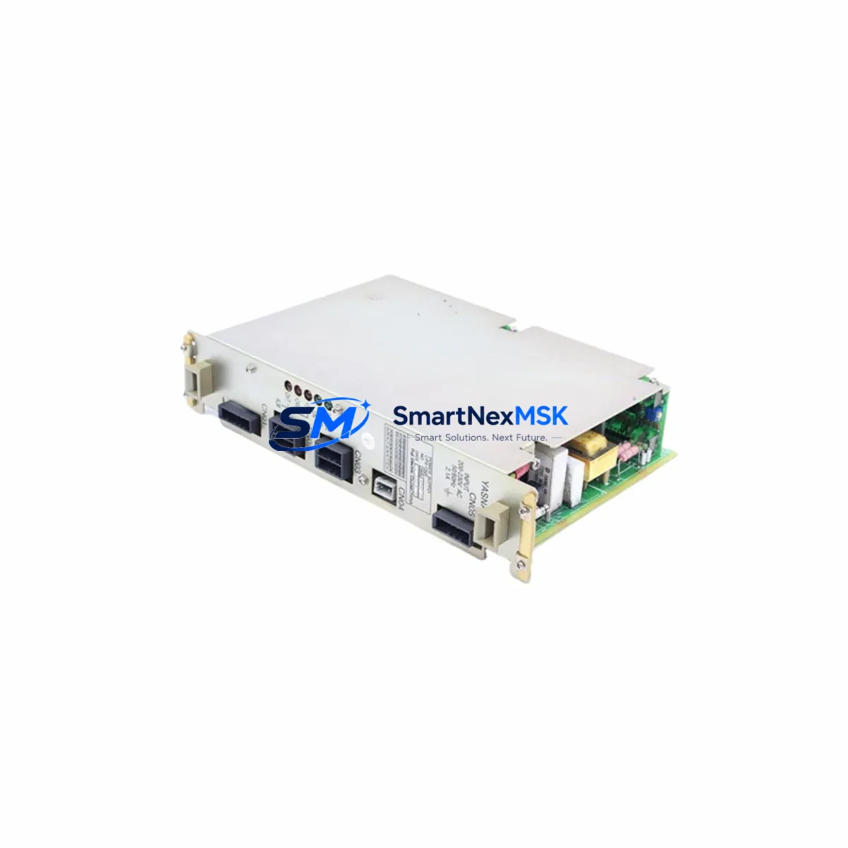
YASKAWA JZRCR-YPU01C-1 Retrofit-Ready Servo Switch-on Unit for JZRCR-YPU Series Control Systems
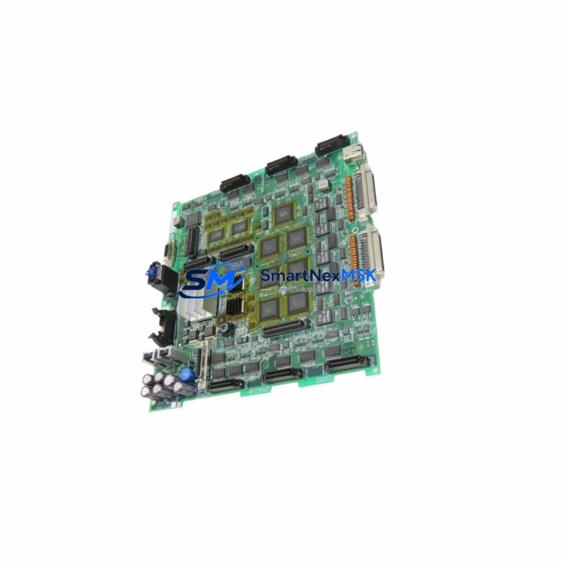
The YASKAWA JZRCR-YPU01C-1 is a servo switch-on unit designed for integration within YASKAWA’s JZRCR-YPU series servo drive and motion control platforms. As legacy automation systems reach end-of-life and OEM support is discontinued, the JZRCR-YPU01C-1 has become a critical retrofit component for engineers tasked with modernizing aging control cabinets, restoring discontinued servo drive assemblies, and maintaining production continuity without full system replacement.
This unit is engineered to serve as a direct replacement for worn or failed switch-on modules within JZRCR-YPU series servo amplifier racks. It is compatible with YASKAWA’s established servo control architecture, supporting the power sequencing and inrush current management functions essential to safe servo drive startup. Engineers retrofitting YASKAWA SGDH or SGDS series servo amplifiers, or maintaining systems built around the JZNC or JZRCR controller families, will find this unit a reliable drop-in solution that preserves existing wiring, backplane connections, and program logic without requiring controller reprogramming.
Upgrade Compatibility Table
| Parameter | Details |
|---|---|
| Part Number | JZRCR-YPU01C-1 |
| Manufacturer | YASKAWA Electric Corporation |
| Compatible Series | JZRCR-YPU, JZNC, SGDH, SGDS Servo Amplifier Racks |
| Function | Servo Switch-on Unit — power sequencing & inrush current control |
| Installation | Backplane slot mount; matches original JZRCR-YPU rack form factor |
| Interface Compatibility | Compatible with YASKAWA MECHATROLINK-II and analog command interfaces |
| Replacement Recommendation | Direct drop-in for failed or end-of-life JZRCR-YPU01C-1 units |
| Commissioning Notes | Verify DC bus voltage, confirm terminal block wiring per original schematic, check module address assignment before power-on |
| Origin | Japan |
| Warranty | 12-Month Warranty — covers manufacturing defects and functional failure under normal operating conditions |
Retrofit Planning for Existing Automation Systems
When planning a retrofit around the JZRCR-YPU01C-1, engineers must account for the full scope of the servo drive assembly. In a typical YASKAWA servo system, the switch-on unit works in coordination with the JZRCR-YPU01B power supply module, which provides regulated DC bus voltage to the servo amplifier rack. Before replacing the JZRCR-YPU01C-1, technicians should verify that the power supply module is delivering correct voltage levels and that no upstream fault has caused secondary damage to the switch-on unit.
The backplane rack — commonly a JZRCR-YPU series multi-axis rack — must be inspected for connector pin integrity and slot alignment. Damaged backplane connectors are a frequent cause of repeated switch-on unit failure and should be addressed before installing the replacement module. In multi-axis configurations, the SGDH-series servo amplifier modules seated in adjacent slots should be powered down and isolated during the swap to prevent cross-fault conditions.
For systems using MECHATROLINK-II communication, the JZRCR-YPU01C-1 replacement does not require re-addressing of the communication network, as the switch-on unit does not carry a MECHATROLINK node address. However, engineers should confirm that the JZNC-YRK01-1E robot controller or equivalent motion controller has not logged persistent servo alarm codes that would prevent the new unit from initializing correctly. Clearing alarm history via the YASKAWA DX100 or DX200 teach pendant before power-on is recommended practice.
I/O wiring connected to the servo enable circuit — typically routed through a JZRCR-YIO series I/O module — should be verified against the original terminal block diagram. Incorrect wiring of the servo-ready or servo-on signal lines is a common commissioning error that can prevent the switch-on unit from completing its startup sequence. Similarly, if the control cabinet includes a JZRCR-YSF01 safety unit, the safety relay chain must be confirmed intact before energizing the replacement module.
HMI screens built on YASKAWA’s proprietary pendant interface or on third-party panels communicating via RS-232 or Ethernet/IP should not require modification following a like-for-like switch-on unit replacement. However, if the retrofit is part of a broader upgrade that includes replacing the JZNC controller with a newer YASKAWA YRC1000 robot controller, HMI program migration and I/O remapping will be required as a separate engineering task.
All replacement units are pre-tested prior to shipment. Stock is maintained to support urgent retrofit and breakdown recovery scenarios, with typical lead times suitable for planned maintenance windows. A 12-month warranty is included, covering manufacturing defects and functional failure under normal operating conditions.
Downtime Control During System Migration
Minimizing unplanned downtime is the primary concern in any servo system retrofit. For the JZRCR-YPU01C-1 replacement, the recommended approach is to prepare the replacement unit and all associated documentation — terminal wiring diagrams, alarm history printouts, and module address records — before the maintenance window begins.
The original program logic stored in the JZNC or YRC1000 controller is not affected by a switch-on unit swap, as program memory resides in the controller, not in the switch-on module. This means that once the physical replacement is complete and wiring is verified, the system can be returned to automatic operation without reprogramming. Engineers should perform a manual jog test of each servo axis before releasing the line to confirm that all axes respond correctly to motion commands.
For production lines where even brief interruptions are costly, it is advisable to maintain a spare JZRCR-YPU01C-1 unit on-site as part of a critical spares inventory. Pairing this with a spare JZRCR-YPU01B power supply module and a set of SGDH series servo amplifiers for the most critical axes provides a comprehensive breakdown recovery kit that can restore full servo functionality within a single shift.
Where the retrofit is part of a scheduled upgrade rather than an emergency repair, the transition can be staged: the new switch-on unit can be bench-tested against a known-good power supply before installation, reducing the risk of introducing a second fault during the maintenance window. Communication link continuity — particularly for MECHATROLINK-II chains — should be verified with a network diagnostic tool before and after the swap to confirm no signal degradation has been introduced.
Retrofit Support FAQ
Q: Is the JZRCR-YPU01C-1 a direct replacement for the original unit without any parameter changes?
A: Yes. The JZRCR-YPU01C-1 is a like-for-like replacement that installs into the same backplane slot and uses the same terminal connections as the original unit. No parameter changes or controller reprogramming are required for a standard swap. Technicians should verify wiring against the original schematic and clear any latched servo alarms before power-on.
Q: What commissioning steps are required after installing the replacement unit?
A: After physical installation, verify DC bus voltage from the JZRCR-YPU01B power supply, confirm all terminal block connections match the original wiring diagram, clear alarm history on the controller (DX100, DX200, or YRC1000 pendant), and perform a manual jog test on each servo axis before returning to automatic operation.
Q: Can this unit be used in systems that have been partially upgraded to newer YASKAWA components?
A: The JZRCR-YPU01C-1 is designed for JZRCR-YPU series racks. In hybrid systems where some components have been upgraded — for example, where a YRC1000 controller has replaced a JZNC unit — compatibility depends on whether the original servo amplifier rack and backplane remain in service. Consult the system wiring diagram and confirm backplane interface compatibility before installation.
Q: What does the 12-month warranty cover?
A: The 12-month warranty covers manufacturing defects and functional failure under normal operating conditions. Units are pre-tested prior to shipment. Warranty claims resulting from incorrect installation, wiring errors, or operation outside specified voltage and environmental parameters are not covered. Contact sales@smartnexmsk.com for warranty support.
© 2026 SMARTNEXMSK. All rights reserved.
Original Source: https://smartnexmsk.com
Contact: sales@smartnexmsk.com | +86 18259474341