Yaskawa JZRCR-YPU01C-1 Retrofit-Ready Switch-On Unit for DX100 Control Systems
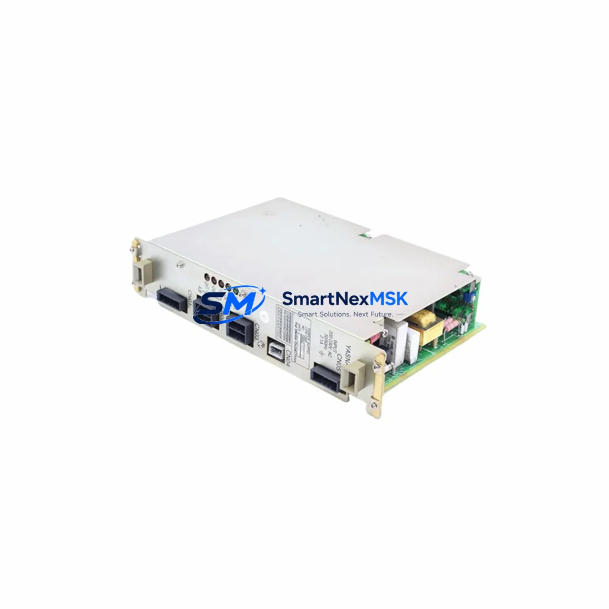
The Yaskawa JZRCR-YPU01C-1 is a Switch-On Unit designed for the DX100 robot controller platform — one of Yaskawa Motoman’s most widely deployed industrial robot control systems. As DX100 controllers age and original spare parts become increasingly scarce, the JZRCR-YPU01C-1 has become a critical component in retrofit projects, legacy system maintenance, and production line continuity programs across automotive, electronics, and general manufacturing sectors.
This unit manages the power sequencing and switch-on logic within the DX100 controller cabinet, coordinating the safe energization of servo drives, I/O modules, and communication boards during system startup. When this component fails or degrades, the entire robot cell is rendered inoperable — making rapid, verified replacement essential to minimizing unplanned downtime.
Our JZRCR-YPU01C-1 units are sourced from authorized distribution channels and undergo pre-shipment functional verification. Each unit ships with a 12-month warranty covering manufacturing defects and functional failures under normal operating conditions.
Upgrade Compatibility Table
| Parameter | Details |
|---|---|
| Compatible Controller | Yaskawa Motoman DX100 |
| Module Function | Switch-On Unit (power sequencing & startup control) |
| Connector Interface | DX100 backplane connector — direct plug-in replacement |
| Installation Requirement | Controller power-off required; ESD precautions recommended |
| Communication Compatibility | Compatible with DX100 internal bus architecture |
| Replacement Recommendation | Direct drop-in for failed or degraded JZRCR-YPU01C-1 units |
| Commissioning Notes | No parameter re-entry required; verify E-stop circuit continuity post-installation |
| Warranty | 12 months from shipment date |
Retrofit Planning for Existing Automation Systems
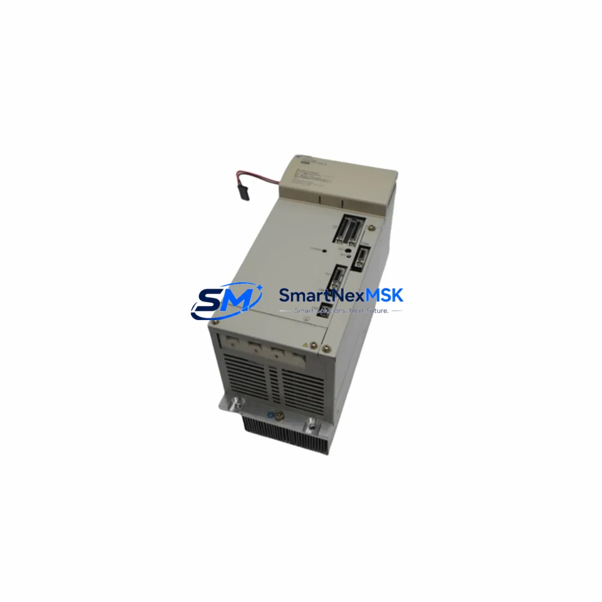
When planning a DX100 controller retrofit or emergency repair, the JZRCR-YPU01C-1 is rarely the only component under evaluation. A thorough retrofit assessment should account for the full controller architecture. The DX100 platform integrates a range of interdependent modules: the JANCD-YCP01-E CPU board governs program execution and axis coordination, while the JZNC-YRK01-1E rack unit provides the physical backplane into which the Switch-On Unit and other boards are seated. Power distribution within the cabinet is managed through the JZRCR-YPS01-1 power supply board, and any degradation in that unit can produce symptoms that mimic Switch-On Unit failure — making parallel inspection advisable.
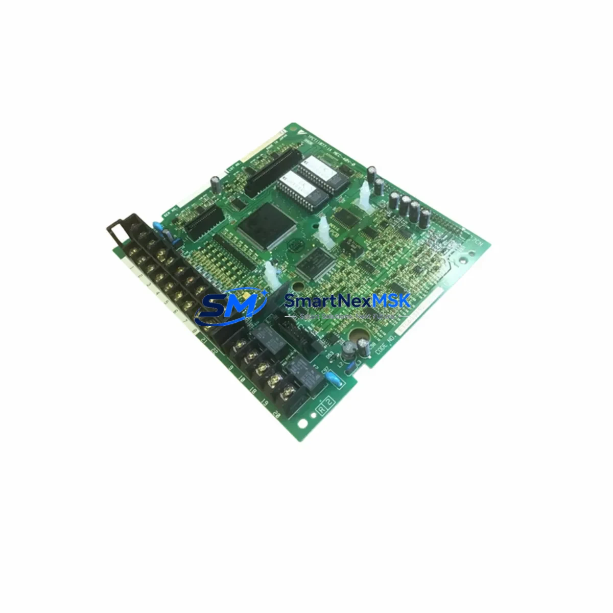
On the I/O side, the JANCD-YIO02-E I/O board handles digital signal interfacing between the controller and field devices such as safety gates, jigs, and peripheral conveyors. If the retrofit involves expanding I/O capacity or migrating from relay-based wiring to solid-state I/O, this board and its terminal assignments must be re-mapped in the system configuration. Similarly, the JANCD-YEW01-E Ethernet communication board is frequently upgraded during DX100 modernization projects to support PROFINET or EtherNet/IP connectivity with newer PLCs or SCADA systems.
For sites running multi-robot cells, the JZRCR-YSU01-1 safety unit and JANCD-YSF21-E functional safety board are critical components to inspect and potentially replace alongside the Switch-On Unit. These modules govern the robot’s safety-rated stop functions and must be validated after any hardware change in the controller cabinet.
HMI integration is another key consideration. Many DX100 installations use the Yaskawa Programming Pendant (JZRCR-YPP01-1 or equivalent) as the primary operator interface. After replacing the JZRCR-YPU01C-1, verify that the pendant communication link is re-established and that all teach program files remain intact on the controller’s internal memory. If the system uses an external HMI panel connected via DeviceNet or RS-232, confirm that the communication parameters have not been reset during the power cycle.
Terminal wiring should be documented before any module swap. The DX100 uses a combination of screw-terminal and connector-based wiring for I/O, servo feedback, and safety circuits. Photograph or export the wiring diagram from the existing installation before beginning disassembly, and verify terminal torque specifications during reassembly to prevent intermittent contact faults.
Downtime Control During System Migration
Unplanned downtime during a DX100 Switch-On Unit failure can cascade quickly in high-throughput production environments. The most effective mitigation strategy is to maintain a verified spare JZRCR-YPU01C-1 on-site as part of a critical spares inventory — particularly for lines where the DX100 controller is no longer covered by an active Yaskawa service contract.
When a replacement is required under production pressure, follow a structured swap procedure: isolate the controller from mains power and allow the capacitor bank in the JZRCR-YPS01-1 power supply to discharge fully before opening the cabinet. Remove the failed Switch-On Unit by releasing the backplane locking tabs, and seat the replacement unit firmly until the connector engages. Do not power on the controller until all boards are fully seated and the cabinet door interlock is confirmed closed.
After power restoration, the DX100 will perform its internal self-diagnostic sequence. Monitor the teach pendant display for alarm codes — particularly alarms in the 4000-series range, which relate to power supply and startup sequencing. If the system clears without alarms, proceed to a dry-run cycle with the robot in low-speed mode before returning to full production speed. This approach preserves the original job programs stored in the JANCD-YCP01-E CPU memory and avoids the need for full system re-teaching, which can represent hours of lost production time.
For planned maintenance windows, coordinate the Switch-On Unit replacement with inspection of the JZRCR-YPS01-1 power board, cooling fan units, and battery backup for the CPU memory. Addressing multiple wear items in a single maintenance window is the most efficient way to extend the operational life of a DX100 controller by several additional years.
Retrofit Support FAQ
Q: Is the JZRCR-YPU01C-1 a direct replacement for all DX100 controller variants?
A: The JZRCR-YPU01C-1 is the standard Switch-On Unit for the DX100 platform. However, DX100 controllers were produced in multiple hardware revisions. We recommend confirming your controller’s production date and hardware revision code (visible on the controller nameplate) before ordering. Our technical team can assist with compatibility verification based on your serial number.
Q: What pre-shipment testing is performed on each unit?
A: Each JZRCR-YPU01C-1 unit undergoes functional power-on testing and visual inspection for connector integrity, PCB condition, and component seating before shipment. Units that do not pass inspection are not dispatched. A test report is available upon request for quality-critical applications.
Q: Do I need to re-enter parameters or reload programs after replacing the Switch-On Unit?
A: No. The JZRCR-YPU01C-1 does not store robot programs or axis parameters — those are retained in the JANCD-YCP01-E CPU board’s battery-backed memory. Replacing the Switch-On Unit does not affect stored job files, system parameters, or I/O assignments, provided the CPU board and its battery remain undisturbed during the swap.
Q: What does the 12-month warranty cover?
A: The 12-month warranty covers manufacturing defects and functional failures under normal operating conditions consistent with the DX100 controller’s rated environment (temperature, humidity, vibration). It does not cover damage resulting from incorrect installation, overvoltage events, or use outside the specified operating parameters. Warranty claims are processed within 5 business days of receiving the returned unit.
© 2026 SMARTNEXMSK. All rights reserved.
Original Source: https://smartnexmsk.com
Contact: sales@smartnexmsk.com | +86 18259474341