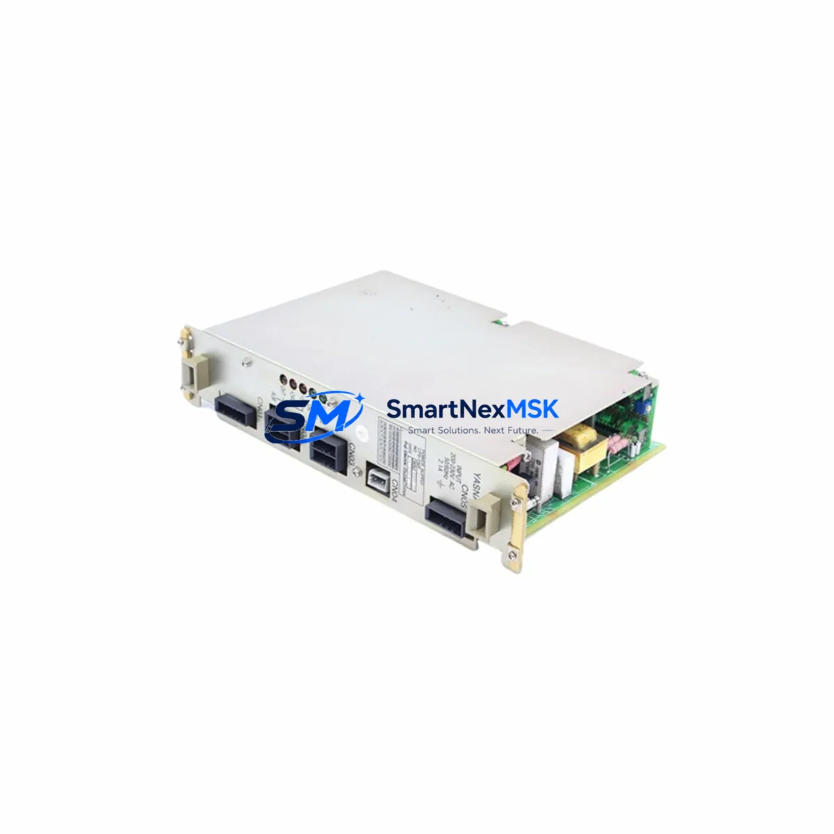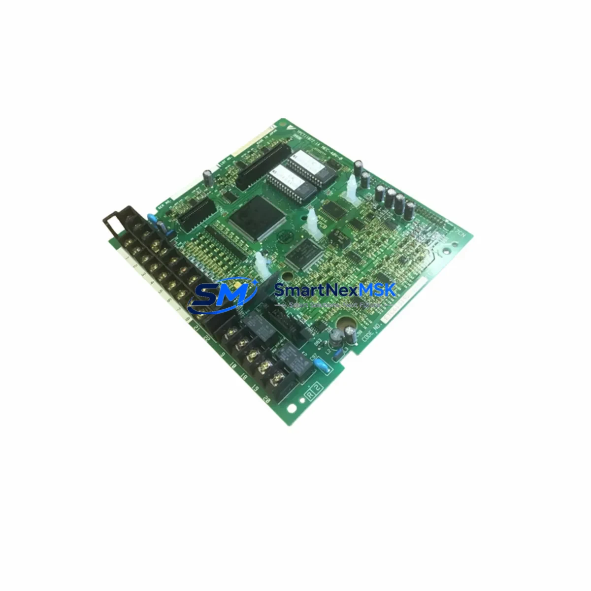
YASKAWA PGB-2K Retrofit-Ready Control Board for Sigma Series: Compatible Upgrade for Legacy Servo Drive Systems
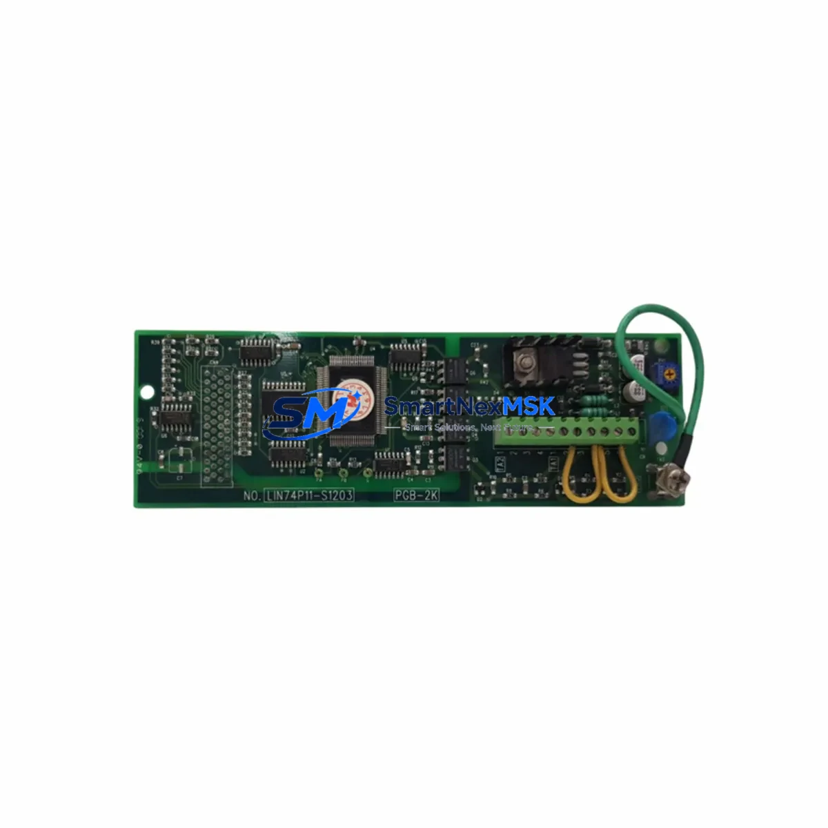
The YASKAWA PGB-2K is a retrofit-ready servo drive control board engineered for direct replacement and smooth integration into existing Sigma Series servo drive systems. As legacy automation lines face increasing pressure from discontinued spare parts, aging backplane connectors, and obsolete firmware, the PGB-2K provides a verified drop-in upgrade path that preserves original control logic, minimizes rewiring, and restores full drive functionality without requiring a complete system overhaul.
Designed for industrial environments where uptime is critical, the PGB-2K is sourced from authorized supply channels, individually tested prior to shipment, and backed by a 12-month warranty. Whether you are managing a planned retrofit or responding to an unplanned drive failure, this board is stocked and ready for fast global dispatch.
Upgrade Compatibility Table
| Parameter | Details |
|---|---|
| Compatible Drive Series | YASKAWA Sigma Series (Sigma-II, Sigma-III, Sigma-V) |
| Replaces / Supersedes | PGB-2K and equivalent legacy control board assemblies in Sigma-series drives |
| Backplane Interface | Standard Sigma-series internal connector; no adapter required for direct-fit models |
| Communication Compatibility | MECHATROLINK-II / MECHATROLINK-III (model-dependent); verify encoder feedback protocol before installation |
| Installation Requirement | ESD precautions required; parameter backup recommended before board swap |
| Retrofit Recommendation | Retain original CN1 wiring harness; re-initialize drive parameters post-installation using SigmaWin+ or equivalent |
| Commissioning Focus | Encoder offset calibration, gain tuning verification, I/O signal mapping confirmation |
| Warranty | 12 months from date of shipment; covers manufacturing defects under normal operating conditions |
Retrofit Planning for Existing Automation Systems
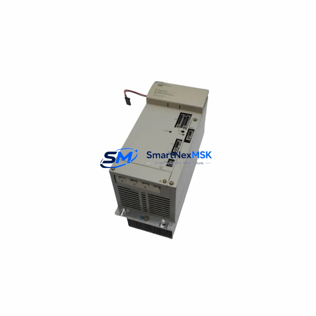
A successful PGB-2K retrofit begins well before the board arrives on-site. Engineers managing Sigma Series servo drive replacements should first conduct a full audit of the existing control cabinet, documenting the drive model number, firmware revision, encoder type, and the CN1 terminal wiring layout. In multi-axis systems, it is common to find the SGDV series servo amplifier or SGDH series amplifier sharing a common DC bus or coordinated motion profile with the affected axis — any parameter changes on the replaced board must be validated against the motion controller’s axis configuration to avoid position offset errors at startup.
Power supply capacity is a critical pre-check. Confirm that the 24VDC control power supply feeding the drive’s logic section can sustain inrush current during board initialization. In retrofit scenarios involving older control cabinets, the original power supply — often a YASKAWA JZRCR-series or equivalent third-party unit — may be operating near its rated output. Adding a new control board without verifying available headroom can cause nuisance trips or unstable drive behavior during the first power-on sequence.
Terminal block wiring should be photographed and labeled before any disassembly. The CN1 I/O connector on Sigma Series drives carries analog reference signals, digital I/O for servo-on, alarm reset, and positioning complete, as well as encoder feedback lines. When replacing the PGB-2K, verify that the CN2 encoder connector and CN3 communication connector seating is secure and that no pins are bent or corroded — a common issue in drives that have been in service for more than five years.
For systems using MECHATROLINK-II communication, confirm that the upstream motion controller — typically a YASKAWA MP2000 series machine controller or a compatible third-party PLC — has the correct axis parameter table loaded. After the board swap, the drive will require re-initialization of the MECHATROLINK node address and baud rate settings. In lines where the SGDV-series drives communicate alongside a YASKAWA JEPMC-series network module, the network scan must be re-executed to re-register the replaced axis.
I/O expansion modules connected to the same control rack, such as YASKAWA SI-ES3 option cards or external relay terminal boards, should be verified for signal continuity after the retrofit. HMI screens — whether running on a YASKAWA GP series operator panel or a third-party touch panel — should be tested for alarm display accuracy and axis status feedback once the drive is back online. Any custom alarm codes mapped to the original board’s firmware version may need to be remapped if the replacement board carries a different firmware baseline.
Programming cables such as the YASKAWA JZSP-CVS06-02-E or equivalent USB-to-serial adapters are required for parameter upload and verification using SigmaWin+ software. Ensure the laptop or engineering workstation has the correct version of SigmaWin+ installed before beginning commissioning — version mismatches between software and drive firmware can prevent parameter read-back and delay the return-to-service timeline.
Downtime Control During System Migration
Minimizing unplanned downtime during a servo drive control board replacement requires a structured pre-swap protocol. Before powering down the affected axis, use SigmaWin+ or the drive’s front panel to perform a full parameter backup to a local file. This backup captures all tuning gains, I/O assignments, encoder settings, and communication parameters — it is the single most important step in protecting the original control logic and ensuring a fast return to production.
Where possible, schedule the board swap during a planned maintenance window rather than responding reactively to a drive fault. Pre-stage the PGB-2K replacement board, the programming cable, a calibrated torque screwdriver for connector fasteners, and a copy of the original drive parameter file before the maintenance window begins. In multi-axis lines, isolate only the affected axis rather than shutting down the entire motion system — most YASKAWA MP-series controllers support axis-level enable/disable without interrupting the remaining axes’ motion programs.
After installing the PGB-2K, restore parameters from the backup file before enabling the servo. Run a no-load jog test at reduced speed to verify encoder feedback direction, then confirm that the position loop closes correctly before returning the axis to automatic mode. Document the commissioning results — including alarm history, gain settings, and test run data — as part of the retrofit record for future reference and warranty support.
For critical production lines where even a brief interruption is unacceptable, consider maintaining a pre-configured spare PGB-2K board with parameters pre-loaded, so that a future swap can be completed in minutes rather than hours. SMARTNEXMSK maintains in-stock inventory of the PGB-2K and can support same-day dispatch for urgent retrofit requirements.
Retrofit Support FAQ
Q1: Is the PGB-2K a direct drop-in replacement for the original Sigma Series control board?
For the majority of Sigma-II and Sigma-III series drives, the PGB-2K is a direct replacement that fits the original backplane connector without modification. However, we recommend confirming the exact drive model number (e.g., SGDH-□□AE, SGDV-□□A01A) before ordering to ensure full pin and firmware compatibility. Our technical team can assist with cross-reference verification prior to shipment.
Q2: What commissioning steps are required after installing the PGB-2K?
After physical installation, restore the parameter backup using SigmaWin+, verify the MECHATROLINK node address and encoder type settings, and perform a no-load jog test to confirm encoder feedback and torque response. Re-check all CN1 I/O assignments against the original wiring diagram. Full commissioning typically takes 1–3 hours depending on system complexity.
Q3: How do I verify wiring compatibility before swapping the board?
Photograph and label all connector positions on the original board before removal. Pay particular attention to the CN1, CN2, and CN3 connectors. Compare the original drive’s wiring diagram (available in the SGDH or SGDV series user manual) against the PGB-2K installation guide. If terminal assignments differ between firmware revisions, contact our technical support team for a wiring adaptation note.
Q4: What does the 12-month warranty cover, and how is it claimed?
The 12-month warranty covers manufacturing defects and component failures under normal operating conditions from the date of shipment. It does not cover damage caused by incorrect installation, overvoltage, or environmental contamination. To initiate a warranty claim, contact sales@smartnexmsk.com with your order number, a description of the fault, and any available alarm codes or SigmaWin+ diagnostic logs. Replacement or repair will be arranged within 5 business days of fault confirmation.
© 2026 SMARTNEXMSK. All rights reserved.
Original Source: https://smartnexmsk.com
Contact: sales@smartnexmsk.com | +86 18259474341