Yaskawa SRDA-SDA71A01A-1 Retrofit-Ready AC Servo Drive for Sigma-III Control Systems
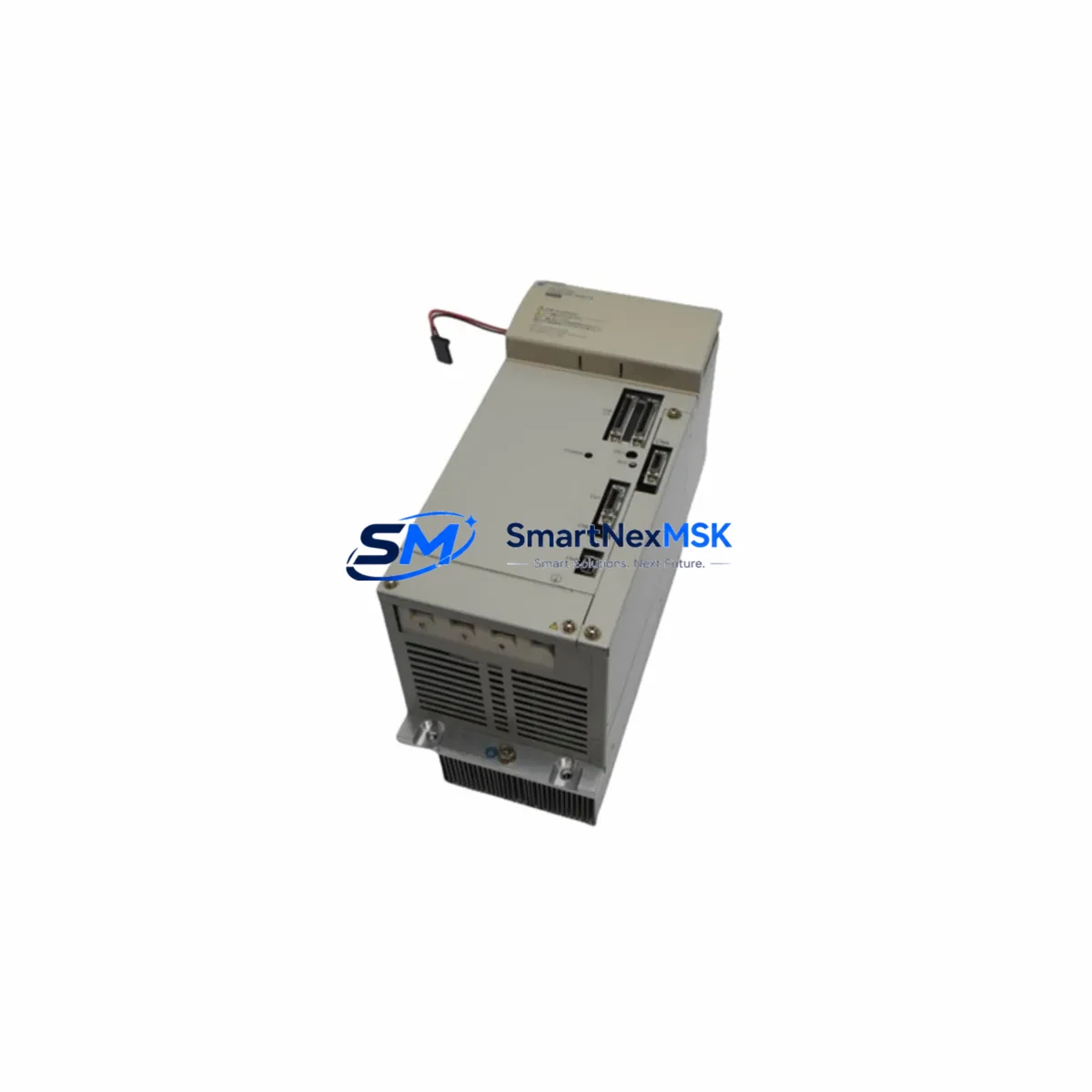
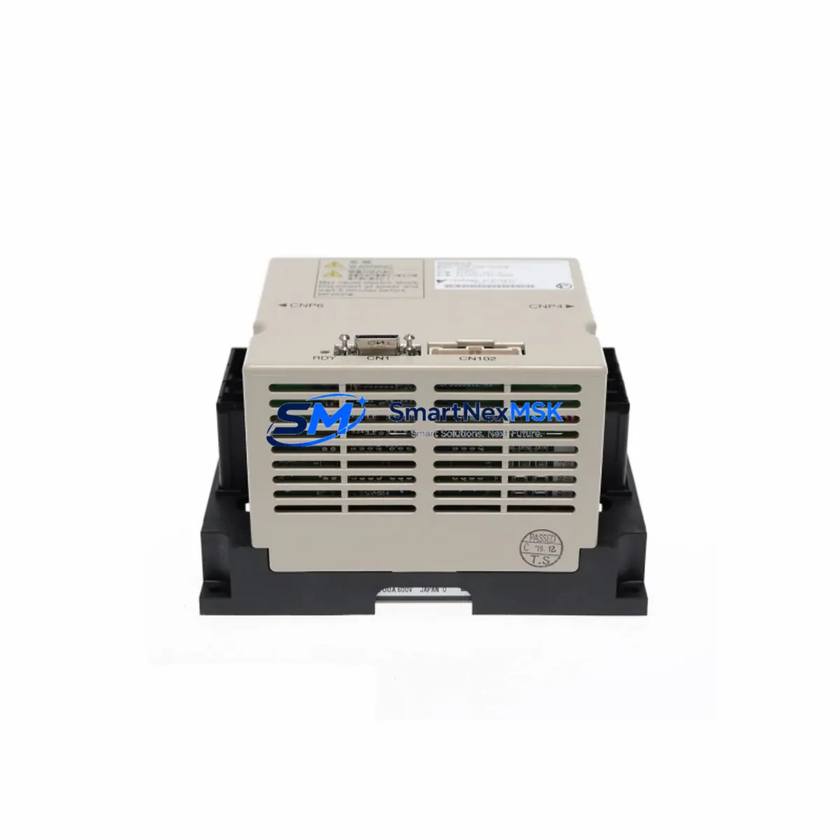
The Yaskawa SRDA-SDA71A01A-1 is a high-performance AC Servo Drive engineered for the Sigma-III series motion control platform. As legacy Sigma-II and early Sigma-III installations reach end-of-service milestones, this drive has become a critical retrofit component for engineers tasked with modernizing aging servo axes without replacing the entire control architecture. Whether you are restoring a discontinued axis, upgrading a multi-axis gantry, or migrating a production line from an obsolete drive model, the SRDA-SDA71A01A-1 provides a verified, drop-in compatible solution backed by a 12-month warranty.
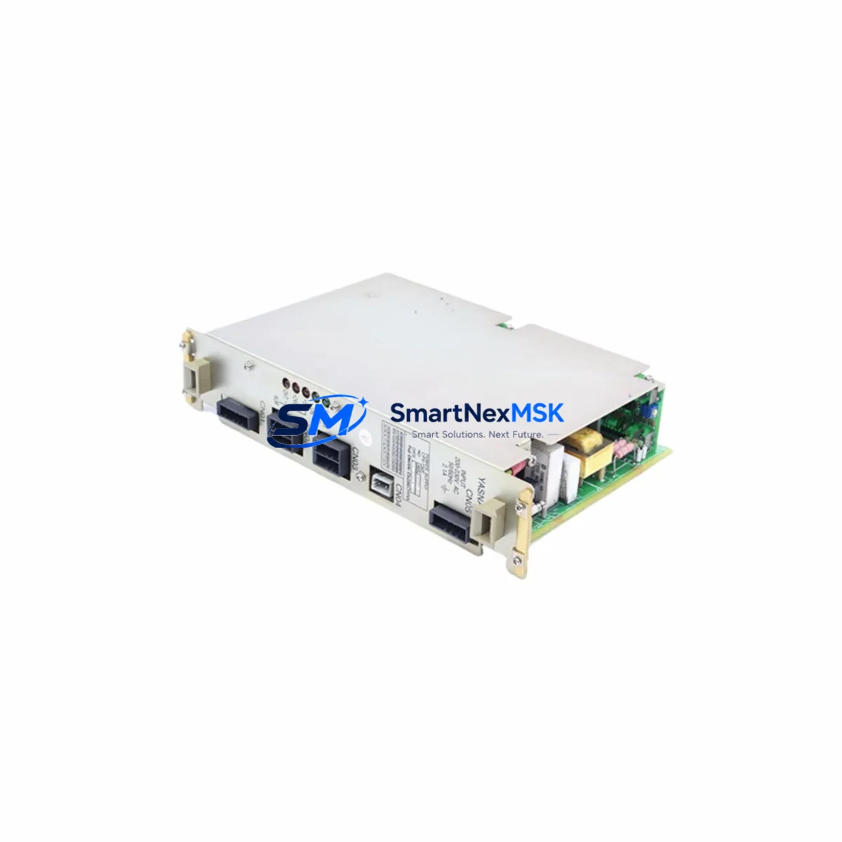
This drive is rated for 7.1 kW continuous output and is designed to interface directly with Yaskawa SGMGH and SGMSH series servomotors. Before installation, engineers should confirm the motor encoder cable pinout, verify the CN1 I/O connector wiring against the existing machine sequence, and check that the power supply capacity at the control cabinet meets the drive’s input voltage and current draw requirements. The SRDA-SDA71A01A-1 accepts three-phase 200 VAC input and requires a dedicated circuit breaker and noise filter — components such as the Yaskawa JZRCR-NPP01B noise filter or equivalent EMC suppression hardware should be verified in the existing panel layout before commissioning.
Upgrade Compatibility Table
| Parameter | Details |
|---|---|
| SKU / Part Number | SRDA-SDA71A01A-1 |
| Series | Sigma-III (SGDS / SRDA) |
| Rated Output | 7.1 kW |
| Input Voltage | Three-phase 200–230 VAC, 50/60 Hz |
| Compatible Motors | SGMGH-□□A□□, SGMSH-□□A□□ series |
| Encoder Interface | 17-bit absolute / incremental (CN2) |
| Host Interface (CN1) | 50-pin I/O connector — analog reference or pulse train |
| Communication | MECHATROLINK-II (optional CN6 module) |
| Replaces / Upgrades From | SGDB-□□AN (Sigma-II), SRDA-SDA71A01A (earlier revision) |
| Mounting / Rack | Panel-mount, DIN rail adapter available |
| Cooling | Built-in fan, forced air — verify cabinet ventilation clearance |
| Commissioning Tool | SigmaWin+ (USB or RS-232 via CN3) |
| Parameter Migration | Export Pn parameters from old drive via SigmaWin+ before swap |
| Warranty | 12 months from date of shipment |
Retrofit Planning for Existing Automation Systems
A successful retrofit of the SRDA-SDA71A01A-1 into an existing Sigma-III or Sigma-II system begins well before the drive arrives on site. The first step is a full audit of the control cabinet: document the existing wiring on the CN1 I/O connector, photograph the terminal block layout, and record all active Pn parameter values from the outgoing drive using SigmaWin+ connected via the CN3 RS-232 or USB interface. This parameter backup is essential — it preserves tuning data, electronic gear ratios, torque limits, and sequence logic that would otherwise require full recommissioning from scratch.
In multi-axis systems, the SRDA-SDA71A01A-1 typically operates alongside other Sigma-III drives such as the SRDA-SDA21A01A-1 (2.1 kW) and SRDA-SDA31A01A-1 (3.1 kW) on a shared MECHATROLINK-II network. Verify that the station address (Pn006) is unique across all nodes and that the network terminator is correctly positioned at the last drive in the chain. If the host controller is a Yaskawa MP2300 Machine Controller or a JEPMC-MP2300-E motion module, confirm that the MECHATROLINK-II scan cycle and axis assignment tables are updated to reflect the new drive’s station address.
On the power side, check that the main circuit power supply — often a Yaskawa SGDR-AXA□□A regenerative converter or a dedicated transformer — can sustain the combined peak current demand of all axes during simultaneous acceleration. The SRDA-SDA71A01A-1 at 7.1 kW has a peak current rating that must be factored into the total bus capacity calculation. If the existing regenerative resistor or braking unit is undersized, add a JUSP-RA□□ dynamic braking resistor before commissioning.
For systems that include a Yaskawa GP7 or GP8 series HMI panel, verify that the servo axis tag names and alarm code mappings in the HMI project still correspond to the new drive’s fault codes. Sigma-III alarm codes differ from Sigma-II in several areas — particularly around encoder faults (A.810, A.820) and overload warnings (A.710) — so HMI screen updates may be required. Similarly, if the PLC ladder logic references specific servo status bits via a Yaskawa CP-9200SH or GL120 controller, validate the I/O map against the CN1 pinout of the SRDA-SDA71A01A-1 before going live.
Finally, inspect the motor power cable and encoder cable for condition and correct shielding. The JZSP-C7M□□-□□-E motor cable and JZSP-CVP□□-□□-E encoder cable are the recommended Yaskawa accessories for this drive-motor combination. Damaged or improperly shielded cables are a leading cause of encoder noise faults and should be replaced as part of any retrofit project.
Downtime Control During System Migration
Minimizing production downtime during a servo drive replacement requires a structured, pre-planned swap procedure. Begin by scheduling the replacement during a planned maintenance window and preparing a rollback plan in case the new drive requires extended tuning. Before powering down, use SigmaWin+ to export the full parameter file (*.prf) from the existing SRDA-SDA71A01A-1 or its predecessor, and store a copy on a dedicated commissioning laptop.
During the physical swap, label every wire on the CN1 connector before disconnecting — a 50-pin connector with unlabeled wires is one of the most common sources of commissioning errors. Retain the original motor cable and encoder cable if they are in good condition; reusing verified cables eliminates one variable from the post-swap diagnostic process. After installing the replacement drive, import the saved parameter file via SigmaWin+ before applying power to the motor circuit. This restores electronic gear ratios, input signal polarity, torque limits, and auto-tuning results, dramatically reducing the time required to return the axis to production-ready status.
Perform a no-load jog test first — confirm direction, speed, and position feedback before engaging the mechanical load. Check for any active alarms (particularly A.040 parameter setting errors or A.C90 encoder communication faults) and resolve them before proceeding to a loaded test cycle. With a well-prepared parameter backup and a clean wiring swap, most SRDA-SDA71A01A-1 retrofits can be completed and verified within a single shift, keeping unplanned downtime to an absolute minimum.
Retrofit Support FAQ
Q1: Is the SRDA-SDA71A01A-1 a direct drop-in replacement for the SGDB-75AN (Sigma-II)?
A: The SRDA-SDA71A01A-1 is not a pin-for-pin drop-in for Sigma-II drives. The CN1 I/O connector pinout and parameter structure differ between generations. A wiring adapter or re-termination of the CN1 connector is required, and all Pn parameters must be re-entered or migrated using SigmaWin+. Motor compatibility should also be verified — Sigma-III drives are optimized for SGMGH/SGMSH motors, while Sigma-II systems often used SGMG/SGMS motors with different encoder specifications.
Q2: What commissioning tools and software are required?
A: SigmaWin+ (version 5.x or later) is the standard commissioning tool. Connect via the CN3 port using a USB-to-RS-232 adapter or a dedicated JZSP-CVS06-02-E USB cable. SigmaWin+ supports parameter upload/download, auto-tuning, alarm history review, and real-time oscilloscope functions. Ensure the software version supports Sigma-III SRDA-series drives before connecting.
Q3: How is pre-shipment testing handled, and what does the 12-month warranty cover?
A: Every SRDA-SDA71A01A-1 unit undergoes functional power-on testing and parameter verification before shipment. The 12-month warranty covers manufacturing defects and component failures under normal operating conditions. It does not cover damage caused by incorrect wiring, overvoltage events, or installation in environments outside the drive’s rated specifications. Warranty claims are processed with a return authorization; replacement or repair is completed and reshipped within the agreed lead time.
Q4: Can this drive operate on a MECHATROLINK-II network alongside other Sigma-III axes?
A: Yes. The SRDA-SDA71A01A-1 supports MECHATROLINK-II communication via the optional CN6 interface module. When integrating into an existing network, assign a unique station address via Pn006, verify the baud rate matches the host controller setting (typically 10 Mbps), and ensure the network terminator plug is installed at the physical end of the MECHATROLINK-II cable chain. Confirm axis assignment in the host controller — such as the Yaskawa MP2300 or JEPMC-CP200 — before enabling the drive on the network.
© 2026 SMARTNEXMSK. All rights reserved.
Original Source: https://smartnexmsk.com
Contact: sales@smartnexmsk.com | +86 18259474341