
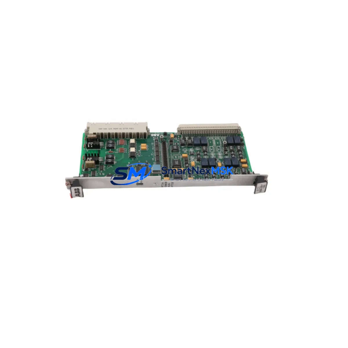
ABB 086387-001 Retrofit-Ready Control Module for AC500 Control Systems
The ABB 086387-001 is a retrofit-ready control module engineered for seamless integration into existing AC500 PLC platforms. Whether you are replacing an end-of-life unit, upgrading a legacy control cabinet, or restoring a production line after an unplanned failure, the 086387-001 delivers the electrical compatibility, communication protocol support, and mechanical form factor required for a smooth, low-risk migration. With verified in-stock availability, factory-tested units, and a 12-month warranty, this module is a trusted solution for industrial engineers managing aging automation infrastructure.
The AC500 series from ABB is widely deployed across process industries, discrete manufacturing, building automation, and energy management. As original equipment ages beyond its supported lifecycle, sourcing a verified replacement for the 086387-001 becomes critical to maintaining uptime. This module supports the same backplane slot assignments and terminal wiring conventions as the original, minimizing the need for panel rewiring or PLC program restructuring during the swap.
Upgrade Compatibility Table
| Parameter | Details |
|---|---|
| Compatible Platform | ABB AC500 PLC Series (PM571, PM581, PM591, PM595) |
| Module SKU | 086387-001 |
| Installation Type | Backplane-mounted, DIN rail compatible rack |
| Communication Protocols | Modbus RTU, PROFIBUS DP, CANopen (platform-dependent) |
| Terminal Wiring | Compatible with original AC500 terminal block layout; verify conductor cross-section per local wiring standard |
| Backplane Interface | Standard AC500 backplane bus; confirm slot address assignment before installation |
| Module Address Config | Address set via hardware DIP switch or software parameter in PS501 Control Builder |
| Program Compatibility | Existing IEC 61131-3 programs compatible; re-download recommended after hardware swap |
| HMI Integration | Compatible with CP600 and CP400 HMI panels; verify tag mapping after replacement |
| Replacement Recommendation | Direct drop-in for 086387-001; cross-reference with PM571-ETH or PM581 if upgrading CPU tier |
| Commissioning Note | Cold-start recommended; verify I/O force flags are cleared before live restart |
| Warranty | 12 Months — covers manufacturing defects and functional failure under normal operating conditions |
Retrofit Planning for Existing Automation Systems
Successful retrofit of the ABB 086387-001 begins with a thorough audit of the existing control cabinet. Engineers should document the current rack configuration, including the TB521 terminal base assignment, the position of any DC532 digital I/O modules, and the slot order of any AI523 analog input modules already installed in the rack. The power supply module — typically a CP502 or CP504 — must be verified for adequate current headroom before adding or replacing modules in the same backplane segment.
Communication architecture is equally important. If the existing system uses a CI502-PNIO PROFINET communication interface module or a CI504-PNIO adapter, the network topology must be preserved during the swap. Any changes to the module’s slot position will alter the PROFIBUS node address or PROFINET device name, requiring corresponding updates in the engineering station running PS501 Control Builder Plus. For systems using a CI541-DP PROFIBUS master module, the GSD file configuration should be exported and archived before the replacement begins.
On the I/O side, engineers should verify that the existing DI524 digital input module and DO524 digital output module wiring harnesses are labeled and photographed before disconnection. Terminal block torque values should be re-applied to specification after reconnection to prevent intermittent contact faults. If the retrofit involves expanding I/O capacity alongside the module replacement, the TB523 terminal base can accommodate additional I/O modules without modifying the existing wiring harness.
For systems with HMI integration, the CP600 panel or CP400 series operator terminal should be placed in offline mode before the module swap. After the 086387-001 is installed and the rack is powered, the HMI project should be re-downloaded to ensure all variable addresses and screen navigation logic remain synchronized with the updated hardware configuration. Any alarm setpoints or recipe data stored in the HMI’s non-volatile memory should be backed up prior to the retrofit.
Programming cable access is required for the initial commissioning step. The TK501 USB programming cable or an Ethernet-connected engineering station running PS501 Control Builder is used to perform the hardware configuration download, verify I/O channel mapping, and confirm that all force flags from the previous installation have been cleared. A full cold-start cycle — power off, wait 30 seconds, power on — is recommended before the first live run to ensure the module initializes cleanly from its default state.
Downtime Control During System Migration
Minimizing production downtime during a control module replacement requires preparation that begins well before the maintenance window. The existing PLC program — including all function block diagrams, structured text routines, and data block configurations — should be exported from PS501 Control Builder and stored on a secure engineering workstation. A second backup copy should be saved to removable media and kept on-site throughout the migration period.
Where process conditions allow, a partial shutdown strategy can be used: isolate the affected rack segment while keeping adjacent racks and field devices energized. This approach preserves communication continuity on the PROFIBUS or PROFINET network and allows the HMI to continue displaying live data from unaffected zones. The 086387-001 replacement can then be completed within the isolated segment, reducing the scope of the outage to a single rack rather than the entire control system.
After the new module is seated and the terminal connections are verified, the program download should be performed with the CPU in STOP mode. Once the download is confirmed complete and the hardware configuration matches the physical rack layout, the CPU can be switched to RUN mode. A staged output enable sequence — bringing outputs online one zone at a time — allows the commissioning engineer to verify field device responses before returning the system to full automatic operation. This approach protects the original program logic, maintains field control continuity, and reduces the risk of process upsets caused by simultaneous output activation across multiple zones.
Retrofit Support FAQ
Q1: Is the ABB 086387-001 a direct replacement for the original module without program changes?
In most cases, yes. The 086387-001 is designed to maintain electrical and functional compatibility with the original AC500 slot assignment. However, a program re-download is always recommended after any hardware swap to ensure the CPU’s hardware configuration table matches the physical rack. No logic changes are typically required unless the replacement is combined with a firmware version upgrade.
Q2: What wiring checks are required before powering up the replacement module?
Verify that all terminal block connections are tightened to the specified torque, conductor insulation is intact, and no cross-wiring has occurred during the swap. Confirm that the power supply module output voltage is within the rated tolerance for the AC500 backplane. Check that any shielded cables connected to analog or communication terminals are grounded at one end only to prevent ground loop interference.
Q3: How is the module address configured after installation?
The module address is assigned either via hardware DIP switches on the module body or through the PS501 Control Builder software during the hardware configuration download. The address must match the slot position defined in the engineering project. If the module is replacing a unit at the same slot position, the existing address assignment in the project file will apply automatically after the program download.
Q4: What does the 12-month warranty cover, and what is the process for a warranty claim?
The 12-month warranty covers manufacturing defects and functional failures occurring under normal operating conditions within the rated electrical and environmental specifications. It does not cover damage caused by incorrect wiring, overvoltage events, or physical mishandling. To initiate a warranty claim, contact [email protected] with the order reference number, a description of the fault, and photographs of the installation. Replacement or repair will be arranged within the warranty period at no additional cost.
© 2026 SMARTNEXMSK. All rights reserved.
Original Source: https://smartnexmsk.com
Contact: [email protected] | +86 18259474341



