
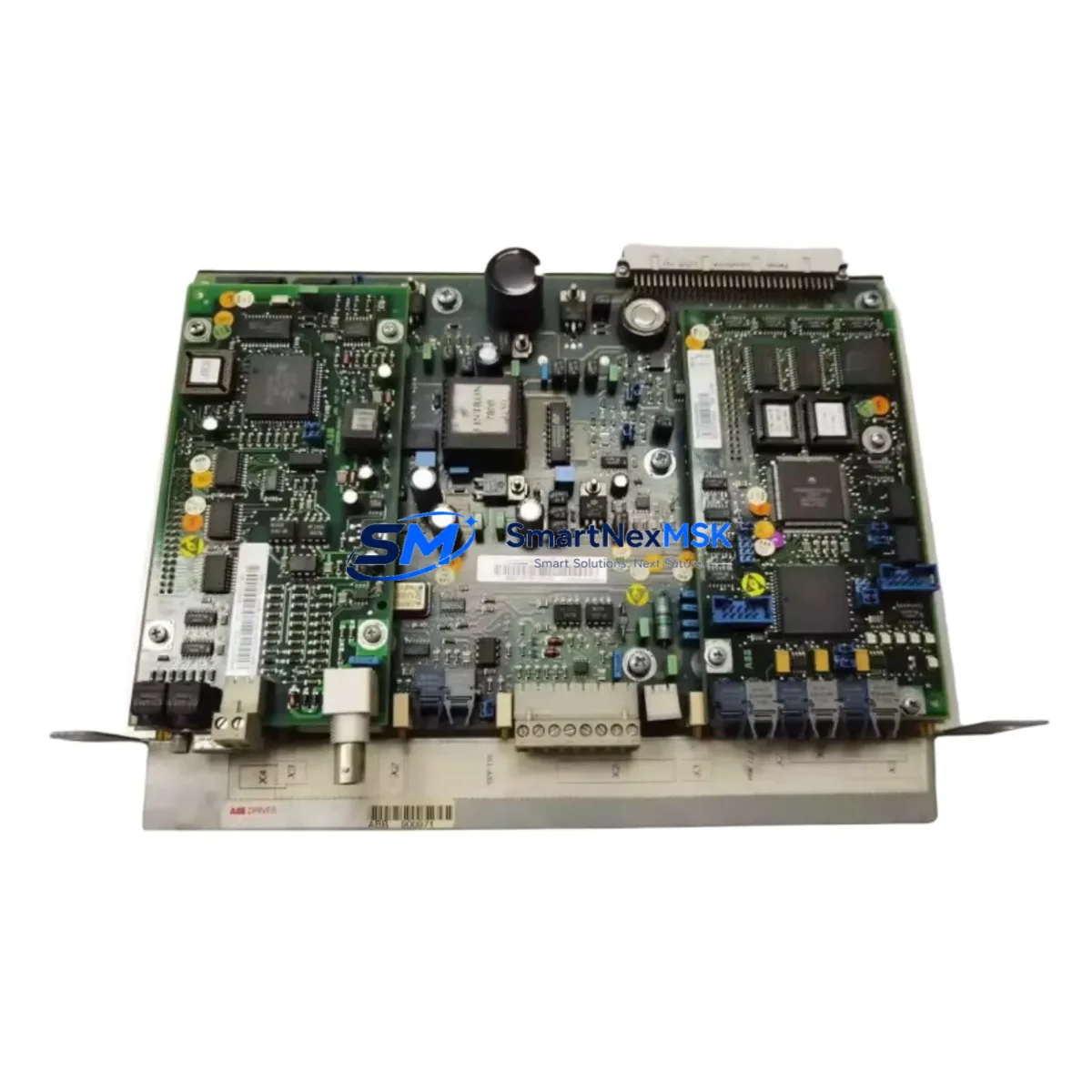
ABB 0YPP110A Maintenance-Ready Spare for ACS800 Automation
The ABB 0YPP110A (also referenced as 3ASD573001A1 / YPK112A) is the RMIO (Relay and Motor I/O) control board at the heart of the ACS800 series AC drive platform. In industrial facilities running continuous processes — paper mills, water treatment plants, compressor stations, conveyor systems, and crane drives — an unplanned ACS800 drive fault caused by a failed RMIO board can halt production within seconds. Stocking a verified original 0YPP110A spare is the single most effective measure a maintenance team can take to compress mean-time-to-repair (MTTR) and protect uptime SLAs.
This listing supplies the original ABB 0YPP110A board, sourced from authorised distribution channels, individually tested prior to dispatch, and backed by a 12-month warranty. Each unit ships with full electrostatic discharge (ESD) packaging and a factory-format inspection record, so your receiving team can log it directly into the spare-parts cabinet without additional incoming inspection overhead.
Spare Maintenance Table
| Parameter | Specification / Value |
|---|---|
| Part Number | 0YPP110A / 3ASD573001A1 / YPK112A |
| Board Function | RMIO — Relay & Motor I/O Control Board |
| Compatible Drive Series | ABB ACS800 (single-drive and multi-drive modules) |
| Supply Voltage (board) | 24 V DC (internal SMPS from drive DC bus) |
| Digital Inputs | 6 × DI (programmable, 24 V DC logic) |
| Digital Outputs | 3 × relay output (250 V AC / 30 V DC, 2 A) |
| Analogue Inputs | 2 × AI (0–10 V / 0–20 mA, 12-bit) |
| Analogue Outputs | 2 × AO (0–20 mA, 12-bit) |
| Fieldbus / Comms Slot | 1 × option module slot (RDCO, RPBA, RCAN, etc.) |
| Encoder / Pulse Input | Supported via RTAC / RTAI option modules |
| Operating Temperature | 0 °C to +55 °C (drive cabinet ambient) |
| Origin | Germany (ABB Drives manufacturing) |
| Installation | Direct board swap; no firmware re-flash required for same firmware revision |
| Compatibility Verification | Match firmware label on existing board before installation |
| Warranty | 12 months from date of dispatch |
| Pre-shipment Test | Functional power-on and I/O continuity test performed on every unit |
Maintenance Planning for Continuous Operation
When a maintenance or reliability engineer schedules a planned outage to replace the 0YPP110A RMIO board, the replacement window is the ideal moment to audit the entire ACS800 control section. Begin with the RDCO-02 or RDCO-04 fibre-optic communication module seated in the RMIO option slot — fibre connectors degrade over time and a cracked ferrule will cause intermittent fieldbus dropouts that are difficult to diagnose after the drive is back online. Inspect the AINT inverter control board and the APOW power supply board simultaneously; both share the same 24 V DC rail as the RMIO and a marginal APOW can cause nuisance RMIO resets that are misdiagnosed as board failures.
Check the AGPS gate driver power supply board for capacitor bulge or discolouration — this board is a common wear item in drives that have operated for more than eight years. While the cabinet is de-energised, inspect the AIMA analogue I/O extension module if fitted, verifying that all terminal screws on the X1 and X2 connector blocks are torqued to 0.5 N·m; loose signal wiring is the leading cause of erratic speed-reference behaviour after a board swap. If the drive uses an RPBA-01 PROFIBUS adapter or an RCAN-01 CANopen module for fieldbus integration, remove and reseat the module to clean the gold-plated edge connector — oxidation on this interface causes communication timeouts that can be mistaken for RMIO firmware faults.
For drives controlling motors above 75 kW, also inspect the ASTO gate unit and the DC bus fuses in the incoming supply section. A weakened fuse that has survived a transient overcurrent event may pass continuity testing but will fail under full-load conditions. Replace the 24 V DC backup battery on the RMIO parameter memory if the drive has been in service for more than three years — a flat battery causes parameter loss on power cycling, which can result in unexpected motor behaviour after a board replacement. Finally, verify that the DDCS fibre ring (if used in a multi-drive system) is intact and that all DDCS addresses are correctly set on the replacement RMIO board before energising.
Site Replacement Workflow
Step 1 — Preparation: Download the ACS800 firmware version from the existing drive’s parameter group 33 (Software Version) before de-energising. Confirm the replacement 0YPP110A board carries the same or a compatible firmware label. If a firmware upgrade is required, arrange the DriveWindow Light laptop tool and DDCS cable in advance to avoid extending the outage window.
Step 2 — Safe Isolation: Follow LOTO (Lockout/Tagout) procedure. Confirm DC bus voltage is below 50 V using a calibrated meter before opening the drive module. The ACS800 DC bus capacitors retain charge for up to 5 minutes after mains disconnection.
Step 3 — Board Removal: Photograph the existing RMIO wiring and option module configuration before disconnecting. Label all ribbon cables and fibre connectors. Remove the RMIO board by releasing the two M3 retaining screws and sliding the board out of the guide rails.
Step 4 — Installation: Insert the replacement 0YPP110A board, reconnect all cables in reverse order, and reseat the option module. Restore parameter group 99 (Start-Up Data) and any application-specific macro parameters from the saved parameter backup.
Step 5 — Commissioning Check: Energise the drive in local control mode. Verify all DI/DO status in parameter group 01 (Actual Values). Run the drive at 10% speed for 2 minutes before returning to process control. Confirm fieldbus communication status and log the replacement in the site maintenance register.
This structured workflow typically achieves a complete RMIO board swap in under 90 minutes, minimising production downtime and eliminating the risk of wiring errors that can damage the replacement board.
Spare Parts Support FAQ
Q1: Is the 0YPP110A compatible with all ACS800 frame sizes?
The RMIO board is common across the ACS800 single-drive range (R2–R8 frame sizes) and ACS800 multi-drive inverter modules. Compatibility depends on firmware revision rather than frame size. Always verify the firmware version on the existing board (visible on the label) matches the replacement unit. Contact our technical team with your drive serial number for confirmation before ordering if you are uncertain.
Q2: What is included in the 12-month warranty?
The warranty covers manufacturing defects and functional failure under normal operating conditions for 12 months from the dispatch date. Each unit is tested prior to shipment. The warranty does not cover damage caused by incorrect installation, overvoltage events, or operation outside the specified environmental range. A warranty claim requires the original dispatch documentation and a fault description.
Q3: Can you supply the 0YPP110A with a firmware upgrade to the latest ACS800 revision?
We supply boards at the firmware revision as received from the authorised supply chain. If a specific firmware version is required, please specify at the time of order. Firmware upgrade services using DriveWindow can be arranged — contact [email protected] with your drive type code and current firmware version for a quotation.
Q4: What is your lead time and do you hold stock?
We maintain buffer stock of high-demand ACS800 spare boards including the 0YPP110A to support emergency replacement requirements. Standard orders ship within 1–3 business days. For urgent breakdown situations, contact us directly at +86 18259474341 to confirm same-day dispatch availability. Long-term supply agreements and consignment stock arrangements are available for facilities operating large ACS800 fleets.
© 2026 SMARTNEXMSK. All rights reserved.
Original Source: https://smartnexmsk.com
Contact: [email protected] | +86 18259474341



