
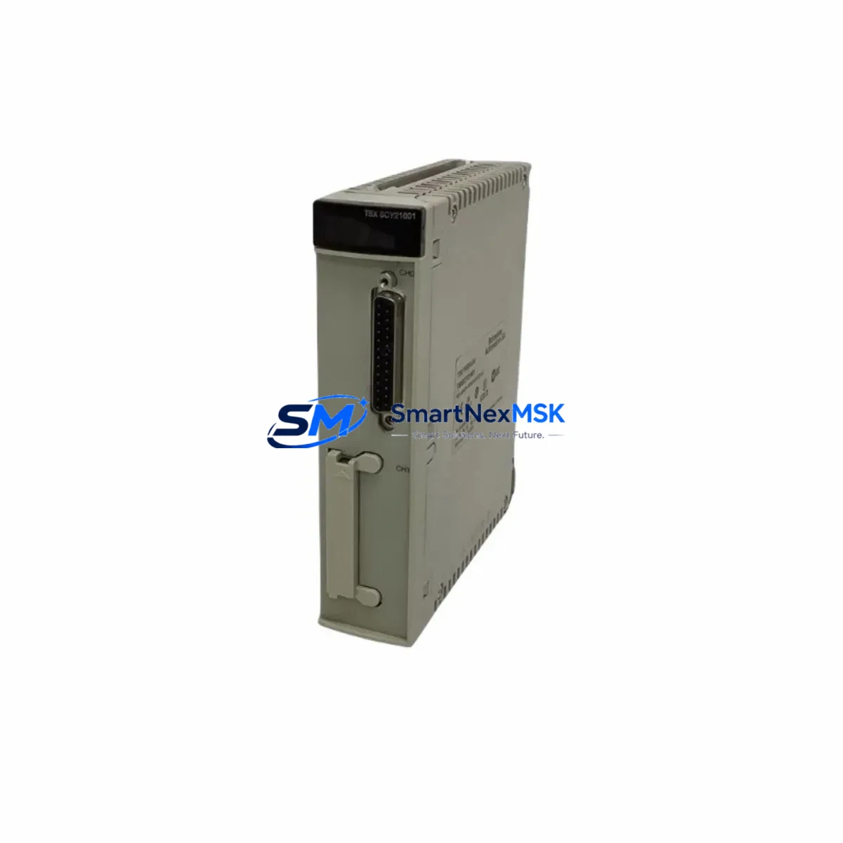
ABB 200-CI485G Maintenance-Ready Spare for AC500 Automation
The ABB 200-CI485G is an original RS-485 serial communication module designed for the ABB AC500 PLC platform — one of the most widely deployed modular programmable logic controller families in industrial automation. For maintenance engineers managing aging control systems, production lines, or critical infrastructure, keeping a verified spare of the 200-CI485G on the shelf is a fundamental risk-reduction strategy. Communication module failures are among the leading causes of unplanned downtime in PLC-based systems: when the RS-485 link drops, field devices go silent, SCADA loses visibility, and production halts. A pre-tested, ready-to-install replacement eliminates the diagnostic delay and procurement lead time that typically extend outages from hours to days.
This unit is sourced as an original ABB component, individually inspected and function-tested prior to dispatch. It ships with a 12-month warranty covering manufacturing defects and operational failure under normal industrial service conditions. Whether you are executing a planned maintenance rotation, responding to an emergency fault, or building out a strategic spare parts inventory for a multi-site AC500 installation, the 200-CI485G is available for immediate fulfillment.
Spare Maintenance Table
| Parameter | Specification |
|---|---|
| Part Number / SKU | 200-CI485G |
| Brand | ABB |
| Series | AC500 (PM5xx / PM5xx-ETH compatible) |
| Module Type | RS-485 Serial Communication Module |
| Communication Standard | RS-485 (EIA-485), half-duplex / full-duplex selectable |
| Supported Protocols | Modbus RTU, Modbus ASCII, free serial (protocol-dependent on CPU firmware) |
| Baud Rate | Up to 115,200 bps |
| Supply Voltage | Supplied via AC500 CPU/expansion bus (no external power required) |
| Operating Temperature | -25°C to +60°C |
| Protection Rating | IP20 (panel-mount, control cabinet installation) |
| Mounting | Direct plug-in to AC500 CPU left-side expansion slot |
| Origin | Germany (DE) |
| Compatibility | AC500 PM571, PM581, PM591, PM595 and ETH variants |
| Certifications | CE, UL (per AC500 platform certification) |
| Warranty | 12 Months — covers manufacturing defects and operational failure |
| Condition | Original, new, tested before shipment |
| Lead Time | In stock — ships within 1–3 business days |
Maintenance Planning for Continuous Operation
When a 200-CI485G failure is identified — whether through a communication fault alarm on the AC500 CPU, a loss of Modbus RTU polling, or a physical inspection during a scheduled cabinet walkdown — the replacement procedure should be treated as part of a broader system health review. Experienced maintenance engineers know that a communication module fault rarely occurs in isolation: the surrounding electrical environment, wiring integrity, and adjacent components all warrant inspection before the new module is commissioned.
Begin with the AC500 CPU module (e.g., PM571-ETH or PM581) itself — verify firmware version compatibility with the replacement 200-CI485G and confirm that the CPU’s internal diagnostics show no secondary faults. Check the 24 VDC power supply module feeding the control cabinet; an unstable or under-rated supply is a common root cause of communication module degradation. Inspect the TB521 or TB541 terminal base that the 200-CI485G mounts into — corrosion, mechanical damage, or a cracked connector can cause intermittent faults that survive a module swap.
On the field wiring side, inspect the RS-485 cable shielding and termination resistors at both ends of the bus. A missing or incorrectly valued termination resistor (typically 120 Ω) will cause reflections that corrupt data at higher baud rates. If the system uses a signal isolator or RS-485 repeater between the AC500 and remote field devices, verify that the isolator is functioning correctly — units from brands such as Phoenix Contact or Weidmüller are common in AC500 installations and should be included in the spare parts checklist.
For I/O integrity, cross-check the DI581 digital input module and DO581 digital output module status via the AC500 diagnostic interface. If the system includes analog signal conditioning, inspect any AI531 analog input modules and associated signal isolators for drift or calibration errors that may have been masked by the communication fault. Where the AC500 communicates upstream to a SCADA or DCS via Ethernet, verify the CM589-PNIO PROFINET module or CM579-ETHCAT EtherCAT module link status as well.
Finally, review the CP600 or CP400 series HMI panel connected to the RS-485 bus — HMI communication parameters (station address, baud rate, parity) must match the new module’s configuration exactly. Document all parameter settings before removing the failed module to ensure a clean, zero-error recommissioning after the 200-CI485G replacement is installed.
Site Replacement Workflow
Step 1 — Fault Confirmation: Confirm the 200-CI485G as the fault source using the AC500 CPU’s built-in diagnostic LEDs and the Automation Builder engineering software. Log the fault code and timestamp for maintenance records.
Step 2 — Safe Isolation: Follow site LOTO (Lockout/Tagout) procedures. The 200-CI485G is hot-swap capable on supported AC500 firmware versions — verify this before attempting live replacement. If hot-swap is not confirmed, de-energize the CPU expansion bus.
Step 3 — Parameter Backup: Export the current CPU project and communication parameters from Automation Builder. Record the RS-485 station address, baud rate, parity, and stop-bit settings configured on the outgoing module.
Step 4 — Physical Replacement: Remove the faulty 200-CI485G from the terminal base. Inspect the terminal base connector pins for damage. Insert the replacement module and confirm the mechanical latch engages fully.
Step 5 — Recommissioning: Power up and verify the CPU recognizes the new module (green RUN LED, no ERR indication). Restore communication parameters via Automation Builder. Confirm Modbus RTU polling resumes and all field device responses are nominal.
Step 6 — Documentation: Update the maintenance log, record the replacement module serial number, and flag the failed unit for return or failure analysis. Replenish the spare parts inventory immediately to restore buffer stock.
Spare Parts Support FAQ
Q1: Is the 200-CI485G compatible with all AC500 CPU variants?
The 200-CI485G is compatible with the AC500 V2 and V3 CPU families, including PM571, PM581, PM591, and PM595 variants (standard and ETH versions). Compatibility with the original AC500 V1 platform (PM5xx first generation) should be verified against the ABB AC500 system manual, as terminal base and firmware requirements may differ. When in doubt, provide your CPU part number and firmware version and our technical team will confirm compatibility before shipment.
Q2: What pre-shipment testing is performed on each unit?
Every 200-CI485G unit undergoes functional verification prior to dispatch: power-on self-test, communication port continuity check, and visual inspection for physical damage. Units that do not pass all checks are quarantined and not shipped. A test report is available upon request for critical infrastructure procurement.
Q3: How should the 200-CI485G be stored as a long-term spare?
Store in original anti-static packaging in a dry environment at 15–35°C with relative humidity below 75% (non-condensing). Avoid proximity to strong magnetic fields or high-vibration areas. Inspect annually for connector oxidation. Properly stored units maintain full operational readiness for 5+ years.
Q4: What does the 12-month warranty cover, and what is the replacement process?
The 12-month warranty covers manufacturing defects and operational failure under normal industrial service conditions. It does not cover damage from incorrect installation, overvoltage events, or physical mishandling. To initiate a warranty claim, contact our support team with the order number, fault description, and photos of the failed unit. Replacement units are dispatched within 3 business days of claim approval, minimizing your system downtime.
© 2026 SMARTNEXMSK. All rights reserved.
Original Source: https://smartnexmsk.com
Contact: [email protected] | +86 18259474341



