
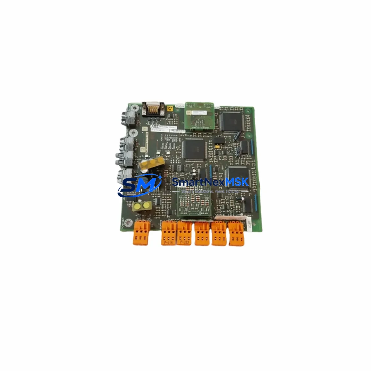
ABB 3002916R0101 Maintenance-Ready Spare for UFC700 Automation
The ABB 3002916R0101 (UFC721AE101) is a critical control module within the ABB UFC700 series Distributed Control System (DCS) platform — a proven architecture widely deployed in power generation, chemical processing, oil & gas, and heavy manufacturing facilities. When this module fails or degrades, the consequences extend beyond a single I/O channel: the entire control loop it governs may go offline, triggering unplanned shutdowns, process deviations, and costly production losses. Stocking a verified replacement unit is the single most effective measure a maintenance team can take to compress mean time to repair (MTTR) and protect operational continuity.
At SMARTNEXMSK, every ABB 3002916R0101 UFC721AE101 unit is sourced from authorized supply chains, subjected to pre-shipment functional verification, and backed by a 12-month warranty. Our inventory is maintained specifically to support emergency callouts, planned turnarounds, and long-term lifecycle extension programs for legacy UFC700 installations.
Spare Maintenance Table
| Parameter | Specification / Detail |
|---|---|
| Part Number | 3002916R0101 |
| Module Designation | UFC721AE101 |
| Compatible Platform | ABB UFC700 Series DCS (Bailey INFI 90 / Harmony) |
| Module Function | DCS Control / Function Module |
| Origin | Germany (DE) — Original ABB Manufacture |
| Operating Voltage | Per UFC700 backplane specification (typically 24 VDC bus) |
| Communication Interface | Module Bus (MFP / INFI-NET compatible) |
| Installation Method | Hot-swap capable rack insertion (UFC700 card cage) |
| Environmental Rating | Industrial — suitable for control room and marshalling cabinet environments |
| Compatibility Verified | UFC700 series card cages; cross-compatible with adjacent UFC721 variants |
| Pre-Shipment Test | Functional verification performed on every unit |
| Warranty | 12 Months from date of shipment |
| Lead Time | In-stock — same-day or next-business-day dispatch available |
| Condition | Original / Refurbished-to-OEM-spec (stated at order confirmation) |
Maintenance Planning for Continuous Operation
Replacing the ABB 3002916R0101 UFC721AE101 in a live UFC700 system is rarely an isolated task. Experienced maintenance engineers treat a module swap as an opportunity to audit the surrounding control cabinet and verify the health of all interdependent components. A structured inspection at the time of replacement significantly reduces the probability of a secondary failure within the same maintenance window.
Begin with the UFC700 backplane and card cage: inspect connector pins for oxidation, confirm backplane bus voltage is within tolerance, and verify that adjacent slots are firmly seated. The UFC760 power supply module feeding the card cage should be load-tested — a marginal power supply is a common root cause of repeated control module faults. If the installation uses a redundant power architecture, confirm that the standby supply switches over correctly.
Next, audit the I/O termination assemblies connected to this module’s signal channels. Loose field wiring, corroded terminal blocks, and degraded cable shields are frequent contributors to intermittent faults that are misdiagnosed as module failures. Check the NTAI09 or NTAI25 analog input termination units (or equivalent digital I/O termination panels) for continuity and insulation resistance. Replace any terminal blocks showing signs of heat discoloration or mechanical wear.
For systems using INFI-NET or Module Bus communications, inspect the UFC760 or NIS (Network Interface Station) communication links. A degraded coaxial segment or faulty BNC terminator can cause the replacement module to report communication errors immediately after installation — a frustrating outcome that is entirely preventable with a pre-swap cable audit. Verify that the MFP (Multifunction Processor) firmware version is compatible with the UFC721AE101 revision being installed.
Signal conditioning components also warrant attention. Signal isolators and loop-powered transmitter barriers in the same I/O loop should be checked for drift; a failing isolator can corrupt the analog signal that the replacement module will now process. Similarly, inspect any relay output modules (such as the NKTU01 or equivalent) that are driven by this control module’s outputs — relay contacts wear independently of the logic module and may need replacement at the same interval.
Finally, review the HMI operator station (e.g., ABB Operate IT or legacy INFI 90 console) to confirm that the module’s tag database and alarm setpoints are correctly loaded after the swap. A configuration backup taken before removal and a post-installation loop test against the process historian will confirm that the replacement is performing identically to the original.
Site Replacement Workflow
Step 1 — Pre-Replacement Preparation: Download the current module configuration using the ABB DCS engineering workstation (e.g., Control Builder or INFI 90 System Engineer). Record all function block assignments, I/O channel mappings, and tuning parameters. Confirm that the replacement 3002916R0101 UFC721AE101 carries the same hardware revision or a confirmed upward-compatible revision.
Step 2 — Safe Isolation: Place the affected control loop in manual mode at the HMI. Notify the process operator and obtain a permit-to-work if required by site safety procedures. For hot-swap capable slots, confirm with the system documentation whether a live swap is supported for this specific module type; if not, schedule the replacement during a planned outage window.
Step 3 — Module Removal and Inspection: Extract the faulty module and inspect the card edge connector and backplane socket for damage. Retain the faulty unit for failure analysis — do not discard until root cause is confirmed. Insert the replacement 3002916R0101 UFC721AE101 and verify that the module status LED sequence matches the expected initialization pattern per the UFC700 hardware manual.
Step 4 — Configuration Restore and Loop Test: Download the saved configuration to the replacement module. Perform a full loop test: inject a known signal at the field termination and verify that the HMI displays the correct engineering-unit value. Check alarm trip points and confirm that control outputs respond correctly in manual and automatic modes.
Step 5 — Return to Service: Transfer the loop back to automatic control, monitor for a minimum of 15 minutes, and document the replacement in the site maintenance management system (CMMS). Update the spare parts inventory record to trigger reorder of a replacement buffer unit.
Spare Parts Support FAQ
Q1: Is the ABB 3002916R0101 UFC721AE101 compatible with all UFC700 card cage variants?
The UFC721AE101 is designed for the ABB UFC700 series card cage architecture. Compatibility with specific cage variants (UFC710, UFC720, UFC730) depends on the backplane revision and firmware level of the host system. We recommend providing your system’s UFC700 model number and software version at the time of inquiry so our technical team can confirm compatibility before shipment.
Q2: What pre-shipment testing is performed on each unit?
Every 3002916R0101 UFC721AE101 dispatched from SMARTNEXMSK undergoes functional power-on verification and, where test fixtures permit, communication bus handshake testing. Units that do not pass verification are quarantined and not offered for sale. A test report is available upon request for critical applications.
Q3: How should I manage long-term spare parts inventory for aging UFC700 systems?
For UFC700 installations that are past OEM active production (ABB has transitioned many UFC700 customers to System 800xA), we recommend maintaining a minimum of one cold-standby 3002916R0101 UFC721AE101 per installed card cage, plus one additional unit per site as a site-level emergency buffer. Modules should be stored in anti-static packaging in a climate-controlled environment and inspected annually. SMARTNEXMSK offers long-term supply agreements to guarantee availability for multi-year maintenance programs.
Q4: What does the 12-month warranty cover, and what is the return process?
The 12-month warranty covers defects in materials and workmanship under normal operating conditions. It does not cover damage resulting from incorrect installation, overvoltage events, or physical mishandling. To initiate a warranty claim, contact [email protected] with the order number, a description of the fault, and any available diagnostic data from the DCS engineering workstation. We will arrange return shipping and provide a replacement or credit within the agreed service level timeframe.
© 2026 SMARTNEXMSK. All rights reserved.
Original Source: https://smartnexmsk.com
Contact: [email protected] | +86 18259474341



