
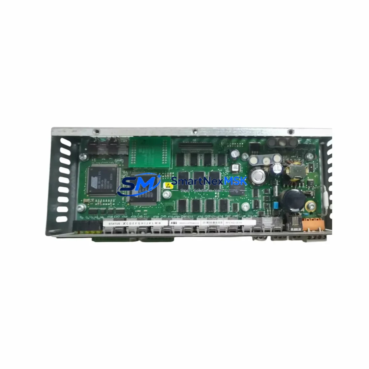
ABB 3010751R0101 Retrofit-Ready DC Drive Control for DCS500/DCS600 Control Systems
The ABB 3010751R0101 is a DC drive control board engineered for direct retrofit and drop-in replacement within ABB DCS500 and DCS600 series DC drive systems. As legacy DCS500 and DCS600 installations approach end-of-service life, plant engineers and maintenance teams face increasing pressure to source reliable, wiring-compatible replacement boards that minimize engineering rework, reduce commissioning time, and protect existing program logic. The 3010751R0101 addresses all of these requirements, making it the preferred choice for industrial facilities undertaking control cabinet upgrades, partial drive modernization, or emergency spare-part replacement.
Whether your facility operates a paper mill, steel rolling line, crane drive system, or extruder line, the 3010751R0101 slots into the existing DCS500 or DCS600 drive chassis without requiring backplane modifications. The board retains full compatibility with the original terminal wiring layout, preserving field wiring integrity and eliminating the need for rewiring the control cabinet. Engineers can reuse existing SDCS-CON-2 and SDCS-CON-4 interface connections, maintaining continuity with the broader drive architecture.
Upgrade Compatibility Table
| Parameter | Details |
|---|---|
| Compatible Series | ABB DCS500, DCS600 |
| Replaces / Supersedes | 3010751R0101 (OEM), compatible legacy control board variants |
| Backplane Interface | Standard DCS500/DCS600 backplane connector — no modification required |
| Terminal Wiring | Direct wiring-compatible; existing field cables reusable |
| Communication Compatibility | DDCS fiber-optic link, PROFIBUS-DP (via NPBA-12 adapter), DeviceNet (via NDNA-02) |
| Installation Requirement | Standard DIN rail / drive chassis mounting; no additional hardware |
| Firmware / Program Compatibility | Compatible with existing DCS500/DCS600 application macros and parameter sets |
| HMI Compatibility | Compatible with CDP312 control panel and DriveWindow PC tool |
| Commissioning Tool | DriveWindow 2.x / DriveWindow Light; parameter upload/download supported |
| Retrofit Recommendation | Verify firmware version before swap; back up parameter set via DriveWindow prior to replacement |
| Warranty | 12 months from date of shipment |
| Origin | Germany |
Retrofit Planning for Existing Automation Systems
A successful retrofit of the ABB 3010751R0101 begins well before the board arrives on site. Maintenance engineers should start by auditing the existing DCS500 or DCS600 drive cabinet to confirm the power supply module — typically the SDCS-POW-1 or SDCS-POW-4 — is delivering stable 24 VDC auxiliary power within specification. An undersized or aging power supply is one of the most common causes of control board instability after replacement, and addressing it proactively prevents repeat failures.
Next, document all terminal block connections on the existing control board before removal. The DCS500 and DCS600 use a structured terminal layout for analog inputs, digital I/O, encoder feedback, and field excitation signals. Photograph or sketch the wiring before disconnecting any terminals. The 3010751R0101 preserves this layout, but verifying wire labeling against the original drive schematic eliminates the risk of transposition errors during reinstallation.
For systems using DDCS fiber-optic communication — common in multi-drive configurations where the DCS600 communicates with an AC800M controller or a Freelance DCS node — confirm that the fiber-optic cable connectors (CH0 through CH3) are clean and undamaged before reconnecting. Dirty or cracked fiber connectors are a frequent source of communication faults that are easily misdiagnosed as board failures.
If the drive system includes an NPBA-12 PROFIBUS-DP adapter or an NDNA-02 DeviceNet adapter mounted on the drive’s option slot, these modules remain in place during the control board swap and do not require reconfiguration, provided the drive node address and baud rate parameters are restored from the backed-up parameter set. Similarly, if the installation uses an NINT-02 or NINT-41 inverter control interface for multi-drive coordination, verify that the DDCS node address is correctly reassigned after the board replacement.
For facilities where the DCS600 drives are supervised by an ABB AC500 PLC or a third-party SCADA system via Modbus RTU, confirm that the communication link is re-established and that the PLC program’s drive status word mapping remains valid after the parameter restore. In some older installations, the HMI screen — often a CP600 or CP620 panel — displays drive status variables mapped directly to drive parameters; verify that these mappings are intact and that the HMI displays correct speed feedback and fault codes after commissioning.
I/O expansion modules connected to the drive’s I/O extension bus, such as the SDCS-IOB-3 analog I/O board or the SDCS-IOB-2 digital I/O board, should be inspected for secure seating in the drive chassis during the retrofit. Loose I/O boards can cause intermittent faults that are difficult to trace after a control board replacement. Confirm that all I/O channel assignments in the drive parameter set match the physical wiring before returning the drive to service.
Downtime Control During System Migration
Minimizing unplanned downtime during a DCS500 or DCS600 control board replacement requires a structured pre-outage preparation protocol. Before scheduling the maintenance window, use DriveWindow or DriveWindow Light to perform a full parameter upload from the existing board and save the parameter file to a secure location. This backup is the single most important step in the entire retrofit process — it allows the replacement 3010751R0101 to be configured to an identical parameter set within minutes of installation, rather than requiring a full recommissioning from factory defaults.
Where production schedules permit, perform a bench test of the replacement board before the planned outage. Connect the 3010751R0101 to a test power supply and verify that the board powers up correctly and that the CDP312 control panel communicates with it. This eliminates the risk of discovering a transit-damaged board during a live production outage.
During the physical swap, follow a structured sequence: isolate the drive from the AC supply and DC bus, discharge the DC link capacitors, remove the fiber-optic connections before the terminal block connections, and reverse this sequence during reinstallation. After reinstallation, restore the parameter set from the DriveWindow backup file, verify the motor identification data (motor nominal voltage, current, speed, and flux), and perform a no-load test run before reconnecting the mechanical load. This sequence typically allows a DCS500 or DCS600 control board replacement to be completed within a two-to-four hour maintenance window, protecting production continuity and reducing the risk of extended unplanned downtime.
For critical production lines where even a brief interruption is unacceptable, consider maintaining a pre-configured spare 3010751R0101 with the parameter set already loaded, so that the replacement can be completed as a direct hot-swap with minimal configuration time.
Retrofit Support FAQ
Q1: Is the ABB 3010751R0101 a direct drop-in replacement for the original DCS500 and DCS600 control board?
Yes. The 3010751R0101 is designed as a direct replacement for the original control board used in ABB DCS500 and DCS600 series DC drives. It uses the same backplane connector and terminal layout, allowing the existing field wiring to be reused without modification. After installation, restore the parameter set from a DriveWindow backup to return the drive to its original operating configuration.
Q2: What commissioning steps are required after replacing the control board?
After physical installation, connect the CDP312 control panel or DriveWindow PC tool and download the previously saved parameter set to the new board. Verify motor data parameters (nominal voltage, current, speed, and flux), confirm I/O channel assignments, and check communication link status if the drive uses DDCS, PROFIBUS-DP, or DeviceNet. Perform a no-load test run to confirm correct speed reference response before reconnecting the mechanical load.
Q3: How do I verify wiring compatibility before removing the original board?
Before disconnecting any wiring, photograph all terminal block connections and cross-reference them against the original drive schematic. The 3010751R0101 preserves the DCS500/DCS600 terminal layout, so existing wire labels and positions remain valid. Pay particular attention to analog input scaling, encoder feedback wiring, and field excitation connections, as these are the most common sources of commissioning errors after a control board replacement.
Q4: What warranty coverage is provided, and has the board been tested before shipment?
All ABB 3010751R0101 units supplied by SMARTNEXMSK carry a 12-month warranty from the date of shipment. Each board undergoes functional testing prior to dispatch to verify power-up integrity and basic communication capability. In the event of a warranty claim, contact our technical support team with the board serial number and a description of the fault condition. Replacement or repair will be arranged promptly to minimize impact on your production operations.
© 2026 SMARTNEXMSK. All rights reserved.
Original Source: https://smartnexmsk.com
Contact: [email protected] | +86 18259474341



