
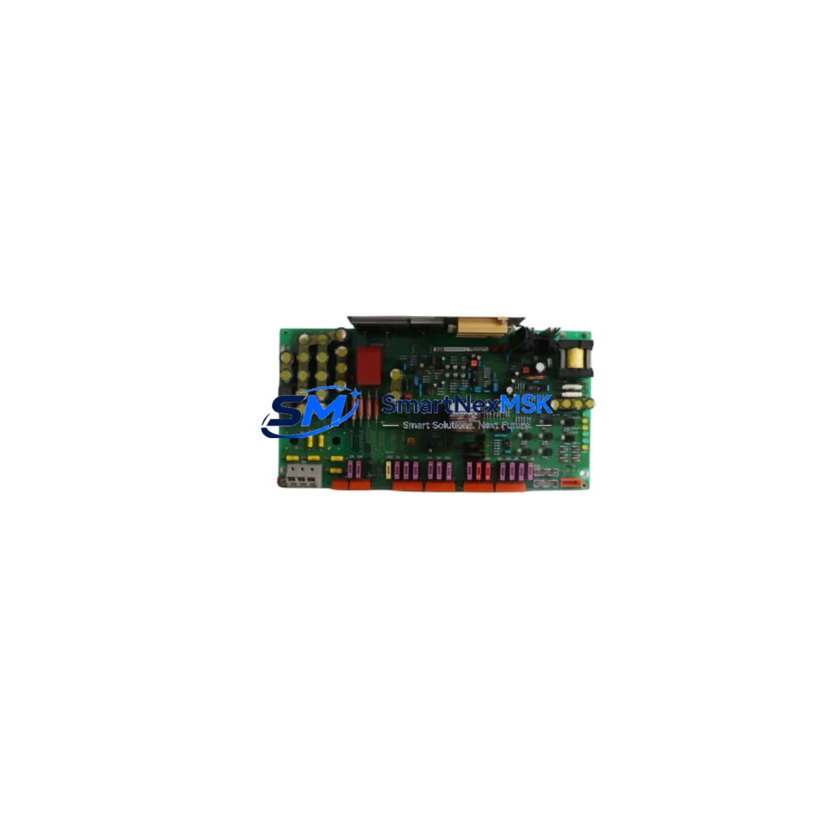
ABB 3BHB003431R0101 KUC720 AE01 Spare for ACS6000 Automation: Minimizing Drive Downtime with Maintenance-Ready Replacement
The ABB 3BHB003431R0101 KUC720 AE01 is the original control board module designed for the ABB ACS6000 medium-voltage (MV) variable speed drive series — one of the most widely deployed MV drive platforms in heavy industry, including oil & gas, mining, marine propulsion, and power generation. When this board fails or degrades, the entire drive train can be forced offline, triggering unplanned production stoppages that cost thousands of dollars per hour.
This listing provides a maintenance-ready, original-specification spare of the 3BHB003431R0101 KUC720 AE01, sourced from authorized supply channels, individually tested prior to shipment, and backed by a 12-month warranty. Whether you are executing a planned overhaul, responding to a fault alarm, or building a strategic spare parts inventory for long-term ACS6000 fleet support, this module is ready for immediate deployment.
Spare Maintenance Table
| Parameter | Specification / Detail |
|---|---|
| Part Number | 3BHB003431R0101 |
| Module Designation | KUC720 AE01 |
| Compatible Platform | ABB ACS6000 Medium Voltage Drive Series |
| Module Function | Drive Control Board — supervisory control, I/O coordination, communication interface |
| Voltage Class | Medium Voltage (MV), 3–36 kV drive systems |
| Origin | Germany (OEM manufactured) |
| Condition | Original / New-equivalent, pre-shipment tested |
| Compatibility | Direct drop-in replacement for ACS6000 control cabinet configurations |
| Communication Interface | DDCS / RDCO fiber-optic compatible (verify with drive firmware revision) |
| Installation Environment | Industrial control cabinet, IP54 enclosure or better recommended |
| Operating Temperature | 0°C to +55°C (standard industrial range) |
| Warranty | 12 Months from date of shipment |
| Lead Time | In stock — ships within 1–3 business days |
| Maintenance Recommendation | Inspect every 12–24 months; replace on fault code F-0001 / A-0001 or control loss events |
Maintenance Planning for Continuous Operation
Replacing the KUC720 AE01 (3BHB003431R0101) is rarely an isolated task. Experienced maintenance engineers know that a control board failure in an ACS6000 drive is often a symptom of broader stress across the control cabinet. A disciplined replacement workflow should include inspection of the following associated components:
Begin with the APBU-44C or APBU-12C pulse encoder interface board, which works in close coordination with the KUC720 to manage motor feedback signals. A degraded encoder interface can cause recurring control board faults even after a fresh KUC720 installation. Next, verify the RDCO-02 or RDCO-03 DDCS communication module — fiber-optic connectors should be cleaned and inspected for micro-fractures that cause intermittent communication loss.
The NPBU-12C or NPBU-44C branching unit distributes control signals across the drive’s inverter modules; any loose fiber connection here will generate misleading fault codes on the new control board. Simultaneously, inspect the 24 VDC auxiliary power supply module feeding the control electronics — an under-voltage condition on the auxiliary rail is a leading cause of premature KUC720 failure and must be ruled out before commissioning the replacement board.
For drives with active cooling, check the NINT-72 or NINT-73 inverter control interface board and the associated AGPS-21C gate driver power supply. These components share the same control bus and thermal environment as the KUC720; degraded gate driver supplies can inject noise that corrupts control board operation. Also review the terminal block wiring and I/O connector harnesses — corroded or loose terminals on the X1/X2 I/O connectors are a common source of intermittent faults that are misdiagnosed as control board failures.
Finally, if the ACS6000 is integrated with an AC800M controller or Symphony Plus DCS via PROFIBUS or Modbus, verify the communication adapter settings and node addresses after board replacement, as firmware-level parameters may reset to factory defaults. Keeping a populated spare parts kit — including the KUC720 AE01, a backup RDCO module, spare fuses for the auxiliary supply, and a set of pre-terminated I/O connector assemblies — reduces mean time to repair (MTTR) from hours to under 30 minutes.
Site Replacement Workflow
Step 1 — Fault Isolation: Confirm the fault is localized to the KUC720 AE01 by reviewing the ACS6000 fault log via the CDP control panel or DriveWindow software. Document all active fault codes (F-xxxx) and alarm codes (A-xxxx) before powering down.
Step 2 — Safe Isolation: Follow the ACS6000 lockout/tagout (LOTO) procedure. Confirm DC bus discharge is complete (minimum 5-minute wait after main contactor opens) before opening the control cabinet door. Use a calibrated voltage tester on the DC bus terminals.
Step 3 — Board Removal: Photograph the existing KUC720 AE01 connector layout before disconnecting. Label all fiber-optic cables with their channel designations (CH1–CH4). Remove the board by releasing the DIN rail clips or rack mounting screws — do not apply lateral force to the PCB.
Step 4 — Replacement Installation: Install the new 3BHB003431R0101 KUC720 AE01 into the same slot. Reconnect all fiber-optic cables in the documented order. Verify the 24 VDC auxiliary supply is within ±5% tolerance before powering up the control section.
Step 5 — Parameter Restore: Upload the saved parameter backup from DriveWindow or the CDP panel. Verify motor control mode (DTC or scalar), speed reference source, and I/O configuration match the pre-fault settings. Run a no-load test before reconnecting the motor load.
Step 6 — Commissioning Verification: Confirm fault-free operation across the full speed range. Log the replacement date, new board serial number, and parameter backup version in the site maintenance record. Update the spare parts inventory accordingly.
Spare Parts Support FAQ
Q1: Is this 3BHB003431R0101 KUC720 AE01 a direct replacement for all ACS6000 variants?
The KUC720 AE01 is the standard control board for the ACS6000 series across most power ratings (3–36 kV, 200 kW–27 MW). However, some early-production ACS6000 units or special-order configurations may use a different board revision. Always cross-reference your drive’s nameplate serial number and the existing board’s part number label before ordering. Our technical team can assist with compatibility verification upon request.
Q2: What pre-shipment testing is performed on this module?
Each 3BHB003431R0101 KUC720 AE01 unit undergoes functional power-on testing, I/O continuity verification, and communication interface checks before dispatch. A test report is available upon request. The 12-month warranty covers manufacturing defects and functional failures under normal operating conditions.
Q3: How should I manage long-term spare parts inventory for ACS6000 drives?
For sites operating 3 or more ACS6000 units, we recommend maintaining at minimum one KUC720 AE01 control board, one RDCO communication module, one set of auxiliary supply fuses, and one APBU interface board as on-site cold spares. For critical continuous-process applications (compressors, pumps, fans), a hot-standby spare strategy with pre-configured parameter backups reduces unplanned downtime risk to near zero.
Q4: What is the warranty and return policy for this spare part?
This module carries a 12-month warranty from the date of shipment. If the unit fails under normal operating conditions within the warranty period, we will provide a replacement or full refund. Units must be returned in original packaging with the fault description documented. Damage caused by incorrect installation, overvoltage events, or environmental contamination is not covered under warranty.
© 2026 SMARTNEXMSK. All rights reserved.
Original Source: https://smartnexmsk.com
Contact: [email protected] | +86 18259474341



