
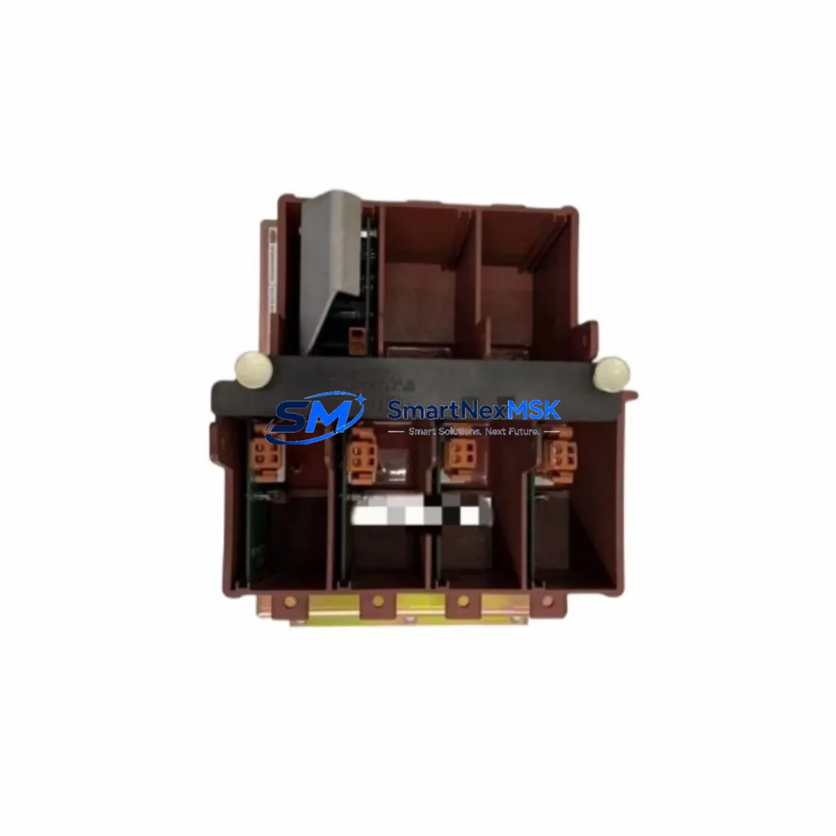
ABB 3BHB005243R0105 KUC755 AE105 Spare ACS800 Automation
When an ACS800 variable frequency drive trips offline on a production line, every minute of unplanned downtime translates directly into lost output and escalating recovery costs. The ABB 3BHB005243R0105 KUC755 AE105 is the original drive power board engineered for the ACS800 series — one of ABB’s most widely deployed industrial drive platforms across pulp and paper, metals, marine, and process automation sectors. Stocking this board as a maintenance-ready spare is a proven strategy for maintenance engineers who need to restore drive operation within a single shift rather than waiting weeks for OEM lead times.
This board serves as the core control and power interface within the ACS800 drive cabinet, managing IGBT gate drive signals, DC bus monitoring, fault diagnostics, and communication with the RMIO or RDCO option boards. Its failure mode — typically manifesting as an F-0001 DC overvoltage fault, F-0002 DC undervoltage, or a complete drive lockout — is one of the most disruptive events in a drive-based automation system. Having a tested, original-specification replacement on the shelf eliminates the diagnostic uncertainty that comes with aftermarket alternatives.
Each unit shipped from SMARTNEXMSK undergoes functional verification prior to dispatch and is covered by a 12-month warranty, giving procurement engineers the confidence to approve the purchase as a long-term inventory asset rather than a one-time emergency buy.
Spare Maintenance Table
| Part Number | 3BHB005243R0105 |
| Board Designation | KUC755 AE105 |
| Brand | ABB |
| Compatible Series | ACS800 (Single Drive & Multi-Drive Modules) |
| Board Function | Drive Power Board — gate drive, DC bus interface, fault logic |
| Nominal Supply Voltage | 24 VDC auxiliary (internal SMPS fed from DC bus) |
| Operating Temperature | 0°C to +55°C (drive cabinet ambient) |
| Origin | Germany (DE) |
| Weight | 3.65 kg (with packaging) |
| Compatibility Verification | Cross-reference ACS800 firmware version and drive frame size before installation |
| Installation Note | ESD precautions required; torque connectors to OEM specification |
| Condition | Original, tested prior to shipment |
| Warranty | 12 Months |
| Application Environment | Industrial — process automation, metals, marine, HVAC, pulp & paper |
| Maintenance Recommendation | Inspect DC bus capacitors and gate resistors during board replacement; log fault history via DriveWindow before swap |
Maintenance Planning for Continuous Operation
A structured maintenance plan for ACS800 drives extends well beyond the power board itself. When a maintenance engineer schedules a planned replacement of the 3BHB005243R0105 KUC755 AE105, the same cabinet inspection window should be used to assess the condition of adjacent components that share the same electrical stress environment.
The RMIO-11C or RMIO-02C control board, which handles the drive’s I/O, fieldbus communication, and application programming, should be checked for firmware currency and connector integrity — a degraded RMIO board can mask or misreport faults that originate in the power board. Similarly, the RDCO-01C or RDCO-02C optical communication module, used in multi-drive configurations, should be inspected for fiber optic cable condition and connector seating.
On the power side, the APOW-01C auxiliary power supply module feeds the control electronics; a marginal APOW unit can cause intermittent resets that are incorrectly attributed to the power board. The AINT-02C or AINT-14C inverter control board, where fitted, should also be logged for fault history before the cabinet is closed.
Procurement engineers building a comprehensive ACS800 spare parts kit should also consider stocking the NINT-41C inverter module interface board, terminal block assemblies for the X1 and X2 I/O connectors, and the drive’s internal 24 VDC fuse set. For drives operating in environments with high harmonic content, the NOCH-01 or NOCH-02 choke module condition should be verified during the same maintenance window. Panel-mounted CDP312R control panels or ACS-CP-C assistant control panels used for local parameter access should be tested for display and keypad function, as these are frequently overlooked until a commissioning engineer needs them during a fault recovery event.
Signal isolation barriers on analog I/O channels feeding the drive’s speed reference and torque reference inputs are another common failure point in aging installations — replacing these proactively during a planned outage prevents nuisance trips caused by ground loop interference rather than actual drive faults.
Site Replacement Workflow
Step 1 — Pre-replacement documentation: Connect DriveWindow or DriveWindow Light to the ACS800 via the DDCS or USB service port. Export the full parameter set and fault log. Record the active firmware version and application macro.
Step 2 — Safe isolation: Follow LOTO (Lockout/Tagout) procedure. Confirm DC bus voltage has discharged below 50 VDC using a calibrated meter before opening the drive module. The ACS800 DC bus capacitor bank retains charge for several minutes after mains disconnection.
Step 3 — Board removal: Photograph all connector positions before disconnection. Label fiber optic cables if RDCO modules are present. Remove the 3BHB005243R0105 KUC755 AE105 board using ESD-safe tools and place it in an anti-static bag for return or failure analysis.
Step 4 — Installation of replacement: Seat the new board, reconnect all connectors in documented order, and torque to OEM specification. Verify that the board revision code matches or supersedes the removed unit — ABB revision history for this board is traceable through the ACS800 Hardware Manual.
Step 5 — Recommissioning: Restore parameters from the exported backup. Run the drive in local control at reduced speed before returning to process control. Monitor DC bus voltage, output current, and heatsink temperature for the first 30 minutes of operation. Clear fault history after confirming stable operation.
This workflow minimizes total downtime to under four hours for a prepared maintenance team, compared to multi-day delays when no spare is available and an emergency OEM order is required.
Spare Parts Support FAQ
Q1: Is the 3BHB005243R0105 KUC755 AE105 compatible with all ACS800 frame sizes?
This board is specific to certain ACS800 frame sizes and drive configurations. Always cross-reference the drive’s type designation plate and the ACS800 Hardware Manual to confirm compatibility before installation. SMARTNEXMSK’s technical team can assist with compatibility verification prior to order confirmation.
Q2: What testing is performed before shipment?
Each 3BHB005243R0105 KUC755 AE105 unit undergoes functional verification on a test bench that replicates the ACS800 operating environment. Power-up, gate drive signal integrity, and communication interface checks are completed before the unit is packaged. A test report is available upon request.
Q3: How should this board be stored as a long-term spare?
Store in the original anti-static packaging in a dry environment between -25°C and +70°C with relative humidity below 95% non-condensing. Avoid storage near strong magnetic fields or high-vibration areas. Inspect the board annually if stored for more than 12 months and re-verify functionality before deployment.
Q4: What does the 12-month warranty cover?
The warranty covers manufacturing defects and functional failures under normal operating conditions consistent with ABB ACS800 specifications. It does not cover damage resulting from incorrect installation, overvoltage events beyond drive ratings, or physical mishandling. Warranty claims are processed with a replacement-first policy to minimize your downtime.
© 2026 SMARTNEXMSK. All rights reserved.
Original Source: https://smartnexmsk.com
Contact: [email protected] | +86 18259474341



