
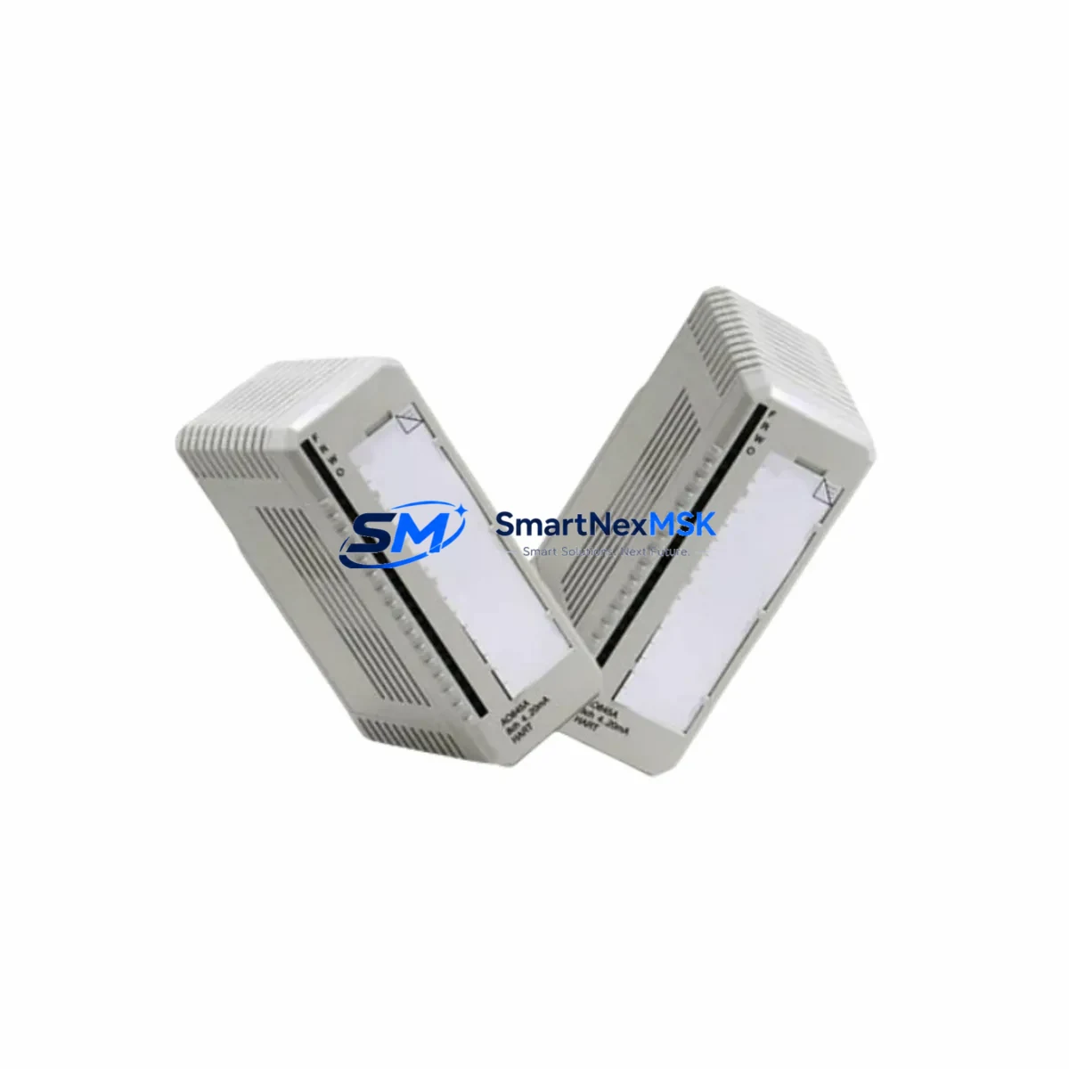
ABB 3BHB006714R0271 SYN5201a-Z Retrofit-Ready Excitation Control for SYN5200 Control Systems
The ABB 3BHB006714R0271 SYN5201a-Z is a retrofit-ready excitation control module engineered as a direct functional replacement for legacy SYN5200 series excitation units. Designed for seamless integration into existing ABB generator excitation and synchronization control architectures, this module supports plant engineers and system integrators tasked with modernizing aging control infrastructure without full system overhaul. Whether you are managing a planned upgrade cycle or responding to an unplanned failure of a discontinued SYN5200 component, the SYN5201a-Z provides a validated migration path that preserves existing wiring topology, terminal assignments, and control logic compatibility.
In retrofit scenarios, the SYN5201a-Z slots into the same backplane position as the original SYN5200 excitation board, eliminating the need for panel re-engineering. Engineers should verify the power supply rail voltage — typically 24 VDC from an ABB SDCS-POW-4 or equivalent power module — before energizing the replacement unit. Terminal block wiring from the field side (AVR feedback, field current sensing, and gate pulse outputs) maps directly to the SYN5201a-Z connector layout, though a point-to-point continuity check against the original wiring diagram is strongly recommended prior to commissioning.
Backplane interface compatibility with the ABB AC800M controller rack or legacy Advant OCS rack should be confirmed against the installed firmware revision. In systems where the SYN5200 communicated via PROFIBUS DP or Modbus RTU, the SYN5201a-Z supports both protocols, and the module address must be re-assigned to match the original node address stored in the PLC program. Failure to align the module address will result in communication faults on the PROFIBUS segment and may trigger safety interlocks on the excitation bus.
For sites running ABB Freelance or Symphony Plus DCS platforms, the SYN5201a-Z integrates with the existing I/O bus without requiring changes to the DCS tag database, provided the function block library version supports the SYN5201 device descriptor. Confirm with your ABB system integrator that the INFI-NET or S+ Operations HMI screens referencing SYN5200 status tags are updated to reflect the new module’s diagnostic register map — this is a common oversight that causes false alarms on the operator workstation after replacement.
During the physical swap, isolate the excitation transformer secondary and discharge the field winding before removing the SYN5200 board. The SYN5201a-Z ships with a factory-default parameter set; site-specific tuning parameters (AVR gain, droop setting, reactive power compensation) must be re-entered via the ABB CMT (Control and Monitoring Tool) or the local keypad interface. Retain a backup of the original SYN5200 parameter file if accessible, as many tuning values transfer directly.
In control cabinet upgrades involving simultaneous replacement of the SDCS-CON-4 converter control board, the SDCS-PIN-51 pulse transformer interface, or the SDCS-FEX-2 field exciter unit, the SYN5201a-Z should be commissioned last in the sequence to allow individual subsystem verification before closing the excitation loop. Sites upgrading from older UNITROL 1000 or UNITROL 5000 excitation regulators to the SYN5201a-Z platform will require a full parameter migration and a staged load test at 25%, 50%, and 100% rated field current.
Communication link verification is critical in multi-drive or multi-generator installations. Confirm that the SYN5201a-Z’s RS-485 termination resistor is enabled only at the physical end of the Modbus chain, and that the PROFIBUS DP segment terminator is correctly positioned. In systems using ABB Panel Builder or ABB CP600 HMI terminals, update the device configuration file (GSD file) to the SYN5201 variant to restore full diagnostic visibility on the operator panel.
All units supplied by SMARTNEXMSK undergo pre-shipment functional testing including power-on self-test, communication port verification, and parameter register integrity check. Each SYN5201a-Z is covered by a 12-month warranty against manufacturing defects, with advance replacement support available for critical plant applications. Stock is maintained for immediate dispatch, with typical lead time of 3–7 business days for international destinations.
Upgrade Compatibility Table
| Parameter | SYN5200 (Legacy) | SYN5201a-Z (Replacement) | Retrofit Notes |
|---|---|---|---|
| Part Number | SYN5200 (various) | 3BHB006714R0271 | Direct functional replacement |
| Backplane Interface | ABB SYN5200 rack slot | Compatible — same form factor | No mechanical modification required |
| Power Supply | 24 VDC (SDCS-POW-4) | 24 VDC | Verify rail voltage before energizing |
| Communication Protocol | PROFIBUS DP / Modbus RTU | PROFIBUS DP / Modbus RTU | Re-assign node address to match original |
| Terminal Wiring | SYN5200 terminal layout | Compatible terminal map | Point-to-point continuity check recommended |
| HMI Compatibility | ABB CP600 / Panel Builder | Compatible with GSD file update | Update device descriptor file on HMI |
| Parameter Migration | SYN5200 parameter file | Re-enter via CMT or keypad | Backup original parameters before swap |
| Installation | DIN rail / rack mount | DIN rail / rack mount | No panel re-engineering required |
| Warranty | — | 12 Months | Advance replacement available |
Retrofit Planning for Existing Automation Systems
A successful SYN5201a-Z retrofit begins with a thorough audit of the existing control cabinet. Identify all interdependent components: the SDCS-CON-4 converter control board governs the firing angle of the thyristor bridge and must be confirmed compatible with the SYN5201a-Z’s gate pulse interface. The SDCS-PIN-51 pulse transformer interface board, if present, should be inspected for capacitor aging — a common failure mode in systems over 10 years old. The SDCS-FEX-2 field exciter unit provides the DC field current and its output calibration must be verified against the SYN5201a-Z’s field current feedback input range.
On the I/O side, review the ABB AI810 analog input modules and DI810 digital input modules connected to the excitation control loop. Any 4–20 mA feedback signals from the generator field winding or AVR measurement circuit should be re-ranged if the SYN5201a-Z’s input scaling differs from the SYN5200. The AC800M controller’s I/O configuration in Control Builder M must reflect any channel reassignments.
For sites with legacy Advant Controller 450 or MOD 300 DCS infrastructure, the SYN5201a-Z can be integrated via a PROFIBUS DP gateway module such as the ABB CI854 PROFIBUS DP interface. Confirm that the gateway’s slot configuration in the DCS engineering tool includes the correct GSD file for the SYN5201 device class. The ABB INSUM motor management system, if installed in the same switchgear lineup, should be checked for any shared PROFIBUS segment with the excitation module to avoid address conflicts.
Programming cable access is required during commissioning: use the ABB NDPA-02 or compatible USB-to-RS485 adapter to connect to the SYN5201a-Z’s local service port. Verify that the CMT software version supports the SYN5201a-Z firmware revision installed on the unit — mismatched versions can prevent parameter upload and may require a firmware update via the ABB service portal.
Downtime Control During System Migration
Minimizing production downtime during an excitation control module replacement requires a structured pre-outage preparation protocol. Before the maintenance window opens, complete all parameter documentation, wiring diagram verification, and spare parts staging. The SYN5201a-Z should be bench-tested with a 24 VDC bench supply and a laptop running CMT to confirm communication and parameter write capability before the unit reaches the plant floor.
During the outage, follow a strict sequence: isolate the excitation transformer, discharge the field winding to zero current (verified by clamp meter on the field leads), remove the SYN5200 board, install the SYN5201a-Z, reconnect all terminals per the verified wiring diagram, and restore power in stages. Do not close the main excitation contactor until the SYN5201a-Z has completed its power-on self-test and the PROFIBUS or Modbus link has been confirmed active from the PLC or DCS side.
Preserve the original PLC program logic unchanged during the hardware swap. The SYN5201a-Z is designed to respond to the same function block calls and register addresses as the SYN5200, so no program modification should be necessary if the module address is correctly assigned. If the site uses ABB Automation Builder or Control Builder M for PLC programming, keep the project file open during commissioning to monitor live I/O values and confirm that excitation feedback signals are within expected ranges before returning the generator to service.
A staged load test — 25%, 50%, and 100% rated field current — should be completed before declaring the system fully restored. Document all as-found and as-left parameter values for the plant maintenance record. Total planned outage time for a prepared team is typically 4–8 hours for a single excitation module replacement.
Retrofit Support FAQ
Q: Is the 3BHB006714R0271 SYN5201a-Z a direct drop-in replacement for all SYN5200 variants?
A: The SYN5201a-Z is functionally compatible with the SYN5200 excitation control platform and shares the same backplane form factor and terminal layout. However, site-specific parameter re-entry is always required, and the HMI device descriptor file must be updated. Confirm your exact SYN5200 variant number with our technical team before ordering if you have a non-standard configuration.
Q: What wiring changes are needed during the swap?
A: In most installations, no wiring changes are required. The SYN5201a-Z terminal map is compatible with the SYN5200 field wiring. A point-to-point continuity check against the original wiring diagram is recommended as a commissioning best practice. If the site has had previous field modifications, verify each terminal against the as-built drawing.
Q: How is the unit tested before shipment?
A: Every SYN5201a-Z supplied by SMARTNEXMSK undergoes a pre-shipment functional test including power-on self-test, communication port verification (PROFIBUS DP and Modbus RTU), and parameter register integrity check. A test report is available upon request. All units are covered by a 12-month warranty from the date of shipment.
Q: What is the lead time and what support is available after delivery?
A: Stock units ship within 3–7 business days internationally. Post-delivery technical support is available via email and phone for commissioning assistance, parameter configuration guidance, and compatibility verification. Advance replacement is available for critical plant applications under the 12-month warranty terms.
© 2026 SMARTNEXMSK. All rights reserved.
Original Source: https://smartnexmsk.com
Contact: [email protected] | +86 18259474341



