
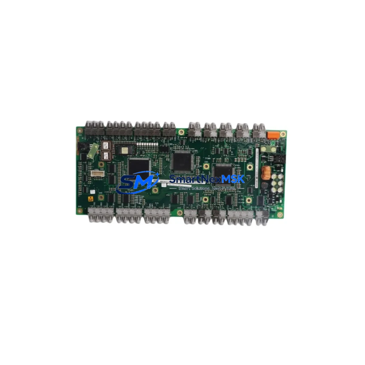
ABB 3BHE004573R0141 UFC760BE141 Retrofit-Ready DCS Interface for Symphony Plus Control Systems
The ABB 3BHE004573R0141 UFC760BE141 is a DCS interface board engineered for seamless integration into ABB Symphony Plus distributed control systems. As legacy Symphony (formerly Harmony and Infi 90) installations reach end-of-life, plant engineers and system integrators increasingly rely on this module to bridge aging field wiring with modern Symphony Plus controllers — eliminating the need for full panel redesigns and minimizing capital expenditure. Whether you are replacing a failed board in a running process line, upgrading a control cabinet to current firmware standards, or migrating from an older communication protocol stack, the UFC760BE141 provides a validated, drop-in compatible solution backed by a 12-month warranty.
This interface board occupies a standard Symphony Plus rack slot and communicates over the ABB proprietary optical INSUM / AF100 fieldbus, making it directly compatible with existing cabling infrastructure in plants that originally deployed Symphony or Harmony DCS architectures. Engineers performing a retrofit do not need to re-engineer the backplane wiring or replace the DSBC 176 bus connection boards already installed in the cabinet — the UFC760BE141 slots in and inherits the existing module address configuration set via the onboard DIP switches.
Upgrade Compatibility Table
| Parameter | Details |
|---|---|
| Compatible Platform | ABB Symphony Plus (S+), Symphony Harmony, Infi 90 |
| Replaces / Upgrades | UFC760BE101, UFC760BE111, UFC760BE121 (earlier hardware revisions) |
| Rack / Backplane Interface | Standard Symphony Plus 19″ rack; compatible with TB820V2 and TB840A processor modules |
| Communication Protocol | AF100 / INSUM optical fieldbus; PROFIBUS DP bridging via optional CI854A coupler |
| Installation Requirement | Module address must match original slot assignment; verify via Control Builder Plus before hot-swap |
| Terminal / Wiring Compatibility | Direct replacement for existing field terminal blocks; no re-termination required in most installations |
| Firmware Compatibility | Compatible with Symphony Plus firmware 5.1 and above; confirm via System Version Manager |
| Debugging / Commissioning | Use ABB Control Builder Plus and System Diagnostic Tool (SDT) for post-swap verification |
| Warranty | 12 months from date of shipment; covers manufacturing defects and functional failure |
Retrofit Planning for Existing Automation Systems
A successful retrofit begins well before the module arrives on site. Start by auditing the existing Symphony Plus rack configuration: confirm the slot position of the failed or obsolete UFC760BE141, document the module node address, and photograph the existing terminal wiring before any disconnection. In most Symphony Plus cabinets, the interface board sits adjacent to the TB820V2 or TB840A processor module and shares the same backplane power rail supplied by the SD821 or SD822 power supply unit. Verify that the power supply output capacity — typically 24 VDC at 6 A — is sufficient to support the replacement board under full I/O load.
For plants running mixed I/O architectures, the UFC760BE141 commonly operates alongside AI810 analog input modules, DI810 digital input modules, and DO810 digital output modules mounted in the same S800 I/O cluster. Before swapping the interface board, confirm that the I/O module addresses are locked in hardware (DIP switch) rather than software-only, as a firmware reset during the swap can cause address conflicts that trigger nuisance alarms on the AC800M controller or the connected PP865 operator panel.
Communication continuity is a critical concern during any DCS interface board replacement. If the plant uses a CI854A PROFIBUS DP communication interface to bridge field devices — including variable frequency drives, smart transmitters, and motor control centers — ensure the PROFIBUS segment remains powered and the CI854A remains online throughout the swap. The UFC760BE141 can be replaced without interrupting the PROFIBUS segment, provided the replacement board is pre-configured with the correct GSD file parameters before insertion. Similarly, if the system uses an AF100 optical ring topology, verify that the ring redundancy is intact and that the replacement board’s optical ports are clean and undamaged before connecting the fiber cables.
For plants that have not yet migrated their HMI layer, the UFC760BE141 retrofit is also an opportunity to validate the 800xA System (formerly Industrial IT) graphic displays against the new module’s data point mapping. Any tag renaming or address offset introduced during the swap must be reflected in the 800xA Aspect Directory before operators resume normal monitoring. Coordinate with the DCS programming team to push a minor Control Builder Plus project update that acknowledges the new hardware revision, and run a full I/O force test on all connected field signals before releasing the loop to automatic control.
Downtime Control During System Migration
Minimizing unplanned downtime during a DCS interface board replacement requires a structured pre-outage checklist and a clear rollback plan. Before the maintenance window opens, export the current Control Builder Plus project to a backup archive and store it on an offline engineering workstation — this preserves the original program logic, function block parameters, and I/O mapping in case the replacement board requires a clean firmware load. If the plant operates a redundant controller pair (e.g., dual AC800M controllers in hot-standby), initiate a controlled switchover to the standby controller before removing the UFC760BE141, so that process control remains active on the secondary path throughout the hardware swap.
During the swap itself, keep the field terminal block connected to the cabinet rail and only disconnect the board-side ribbon or backplane connector. This approach preserves field wiring continuity and allows a rapid reconnection if the replacement board needs to be returned for testing. Once the new UFC760BE141 is seated and the backplane connector is secured, power up the rack and observe the module status LEDs: a steady green RUN indicator confirms successful backplane communication, while a flashing red FAULT LED indicates an address conflict or firmware mismatch that must be resolved before returning the loop to service.
Post-swap commissioning should include a live signal verification on all I/O channels associated with the replaced board, a communication link test on the AF100 or PROFIBUS segment, and a review of the 800xA alarm summary to confirm no latent faults were masked during the outage. Document the as-found and as-left conditions, record the replacement board’s serial number, and update the plant’s spare parts register. With proper preparation, a UFC760BE141 swap can be completed within a two-hour planned outage window, keeping production impact to an absolute minimum.
Retrofit Support FAQ
Q1: Is the 3BHE004573R0141 UFC760BE141 a direct drop-in replacement for earlier UFC760BE revisions?
In most Symphony Plus installations, yes. The UFC760BE141 is hardware-revision R0141, which supersedes R0101 and R0111. The backplane connector, module form factor, and address DIP switch layout are identical. However, confirm firmware compatibility using ABB’s System Version Manager before installation, as some early Symphony Harmony racks running firmware below version 5.0 may require a firmware update on the processor module before the new board is recognized.
Q2: Can I replace the UFC760BE141 without shutting down the entire DCS?
Yes, provided the system is configured with controller redundancy and the I/O cluster associated with this board is not in a safety-critical interlock path. Initiate a controlled switchover to the standby AC800M controller, place the affected I/O in manual mode at the 800xA operator station, and proceed with the hot-swap. Restore automatic control only after the replacement board passes the post-swap I/O verification test.
Q3: What wiring changes are required when installing the replacement board?
Typically none. The UFC760BE141 uses the same backplane interface as its predecessors, and field wiring terminates on the S800 I/O terminal blocks rather than directly on the interface board. If the existing terminal blocks (e.g., TB820V2 termination units) are in good condition, no re-termination is required. Inspect the backplane connector pins for corrosion or mechanical damage before seating the new board.
Q4: What does the 12-month warranty cover, and how is it claimed?
The 12-month warranty covers manufacturing defects and functional failure under normal operating conditions. It does not cover damage caused by incorrect installation, overvoltage, or environmental contamination. To claim warranty service, contact [email protected] with the module serial number, purchase order reference, and a description of the fault. Replacement or repair will be arranged within 5 business days of fault confirmation. All units are function-tested prior to shipment to minimize the risk of DOA (dead-on-arrival) failures.
© 2026 SMARTNEXMSK. All rights reserved.
Original Source: https://smartnexmsk.com
Contact: [email protected] | +86 18259474341



