
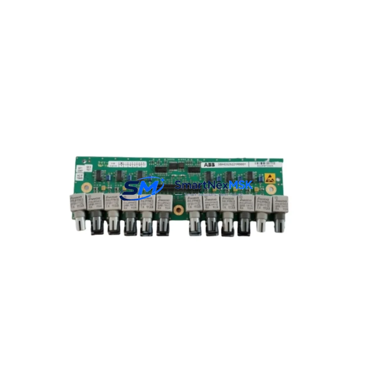
ABB 3BHE019361R0101 UFD203A101 Spare for UFD203A Automation: Spare Parts Replacement & Industrial Downtime Risk Control
The ABB 3BHE019361R0101 UFD203A101 is an original excitation control module designed for ABB’s UFD203A series automation systems, widely deployed in power generation, heavy industry, and process control environments. When this module fails or degrades, the consequences extend far beyond a single component — excitation loss can trigger generator trips, cascade protection faults, and unplanned shutdowns that cost thousands per hour. Stocking a verified replacement spare is the most effective strategy for minimizing mean time to repair (MTTR) and maintaining continuous operation.
Maintenance engineers working on ABB excitation systems recognize the UFD203A series as a critical subsystem. The 3BHE019361R0101 module governs field current regulation and interfaces directly with the AVR (Automatic Voltage Regulator) control loop. Any degradation in this module — whether from thermal cycling, capacitor aging, or transient overvoltage — can manifest as unstable generator output, reactive power oscillation, or hard fault trips. Proactive spare holding eliminates the lead-time risk associated with OEM procurement channels, which can stretch from weeks to months for legacy excitation hardware.
From a procurement engineering perspective, the UFD203A101 variant designation confirms the specific hardware revision and firmware compatibility level required for direct drop-in replacement. Substituting an incorrect revision can introduce parameter mismatches with the UNITROL excitation controller, requiring re-commissioning and extended downtime. Our supply chain maintains traceability documentation and pre-shipment functional verification for every unit dispatched.
Spare Maintenance Table
| Parameter | Specification |
|---|---|
| Part Number | 3BHE019361R0101 |
| Module Designation | UFD203A101 |
| Brand / Manufacturer | ABB (ASEA Brown Boveri) |
| Series | UFD203A — UNITROL Excitation Control |
| Product Type | Excitation Control Module |
| Origin | Germany (DE) |
| Compatible Systems | ABB UNITROL 5000 / 6000 series AVR, UFD203A excitation panels |
| Application Environment | Power plant generator excitation, industrial AVR control cabinets |
| Installation Type | DIN-rail / backplane slot mount (per UFD203A panel configuration) |
| Operating Temperature | 0°C to +55°C (storage: -25°C to +70°C) |
| Humidity | 5–95% RH, non-condensing |
| Weight | Approx. 3,200 g (packaged) |
| Maintenance Recommendation | Replace at first sign of output instability; inspect every 24 months |
| Warranty | 12 Months from shipment date |
| Pre-shipment Testing | Functional verification performed on every unit |
| Supply Condition | Original spare, new or refurbished-to-spec with full traceability |
Maintenance Planning for Continuous Operation
Replacing the 3BHE019361R0101 UFD203A101 in the field is rarely an isolated task. Experienced maintenance engineers treat excitation module replacement as an opportunity for a broader control cabinet inspection. Before returning the system to service, the following associated components should be evaluated.
The ABB UNITROL 5000 / 6000 AVR main control board should be inspected for firmware version alignment with the replacement UFD203A101 module — mismatched revisions are a common source of post-replacement instability. The UFD203A field current feedback card (typically mounted adjacent to the excitation module) should be checked for connector corrosion and signal integrity, as degraded feedback signals can mask the true source of excitation faults.
Power supply modules feeding the excitation panel — including the ABB PSTX or equivalent 24 VDC auxiliary power supply — should be load-tested, since a sagging auxiliary rail is a frequent but overlooked contributor to excitation module failures. Terminal blocks and wiring harnesses connecting the UFD203A module to the field winding circuit should be inspected for thermal discoloration, loose crimps, and insulation breakdown, particularly in high-ambient-temperature installations.
The ABB REX521 or REG670 generator protection relay interfacing with the excitation system should have its excitation loss (40) and field overcurrent (24) protection elements verified after module replacement to confirm correct pickup settings. If the installation includes a power system stabilizer (PSS) function card within the UNITROL platform, its analog I/O connections should be re-verified following any excitation hardware change.
For older UFD203A installations, the fiber optic communication links between the excitation controller and the plant DCS or SCADA system should be cleaned and tested — fiber degradation is a silent fault that only becomes apparent under load. Additionally, the crowbar protection thyristor module and associated field discharge resistor should be inspected for signs of thermal stress, as these components absorb energy during field forcing events and are often overlooked in routine maintenance cycles.
Procurement engineers building a comprehensive spare parts list for UFD203A-based excitation systems should also consider holding a spare ABB 3BHE022453R0101 gate driver board and a set of UFD203A series fuse elements rated for the field circuit, ensuring that a single component failure does not extend downtime beyond the replacement window.
Site Replacement Workflow
Step 1 — Pre-replacement verification: Confirm the incoming spare’s part number (3BHE019361R0101) and revision code (UFD203A101) match the installed unit exactly. Cross-reference the excitation panel nameplate and the UNITROL controller configuration file to validate hardware revision compatibility before de-energizing.
Step 2 — Safe isolation: Follow the site LOTO (Lockout/Tagout) procedure for the generator excitation circuit. De-energize the auxiliary 24 VDC supply to the UFD203A panel before disconnecting the module. Verify zero voltage on the field winding terminals using a calibrated meter.
Step 3 — Module extraction and inspection: Remove the faulty 3BHE019361R0101 module and inspect the backplane connector for bent pins, carbon tracking, or moisture ingress. Clean the connector with approved contact cleaner before installing the replacement.
Step 4 — Installation and parameter restore: Seat the replacement UFD203A101 module firmly into the backplane. Restore any module-level parameters from the site configuration backup. If no backup exists, parameters must be re-entered from the commissioning record — do not assume factory defaults are correct for the installed application.
Step 5 — Functional test before re-energization: Apply auxiliary power and verify the module’s status LEDs indicate healthy initialization. Perform a no-load excitation test at reduced field current before returning the generator to full load. Monitor reactive power output and AVR response for at least 15 minutes under stable load conditions.
This workflow reduces replacement-related downtime to under 4 hours for a prepared maintenance team, compared to multi-day outages when spare parts are sourced reactively. Long-term, maintaining a dedicated UFD203A spare holding — including the 3BHE019361R0101 module — is the most cost-effective strategy for aging excitation systems where OEM support timelines are unpredictable.
Spare Parts Support FAQ
Q1: Is the 3BHE019361R0101 UFD203A101 a direct replacement for earlier UFD203A revisions?
The UFD203A101 revision designation indicates a specific hardware and firmware baseline. In most cases it is backward-compatible with earlier UFD203A panel configurations, but parameter re-entry may be required if the previous module carried a different revision. Always verify against the site commissioning record and UNITROL controller firmware version before installation.
Q2: What pre-shipment testing is performed on each unit?
Every 3BHE019361R0101 UFD203A101 module dispatched from our facility undergoes functional power-on verification, output signal integrity testing, and visual inspection for connector and PCB condition. A test report is available upon request. Units are packed in anti-static, shock-absorbing packaging to maintain condition during international transit.
Q3: How should this spare be stored if not immediately installed?
Store the module in its original anti-static packaging in a dry, temperature-controlled environment (10°C–30°C, less than 70% RH). Avoid storage near strong magnetic fields or high-vibration areas. Inspect the module annually if held in long-term storage, and re-verify functionality before installation if stored for more than 24 months.
Q4: What does the 12-month warranty cover?
The 12-month warranty covers manufacturing defects, functional failure under normal operating conditions, and DOA (dead on arrival) units. It does not cover damage resulting from incorrect installation, overvoltage events beyond rated limits, or unauthorized modification. Warranty claims are supported with return shipping coordination and priority replacement dispatch to minimize site downtime.
© 2026 SMARTNEXMSK. All rights reserved.
Original Source: https://smartnexmsk.com
Contact: [email protected] | +86 18259474341



