
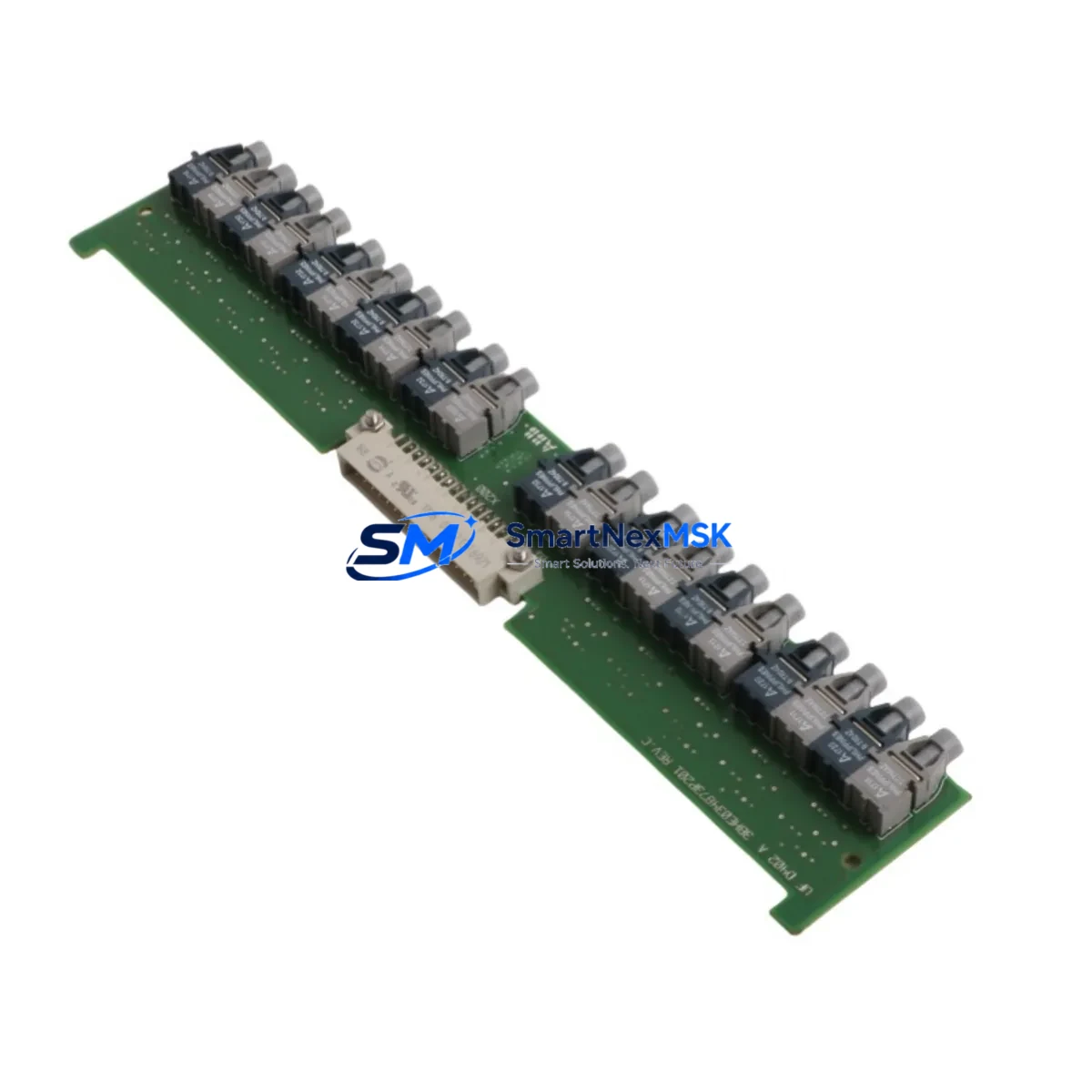
ABB 3BHE034872R0101 UFD402A101 Retrofit Drive Control Board: Compatible Upgrade for Legacy ACS Drive Systems
The ABB 3BHE034872R0101 UFD402A101 is a drive control board engineered for the UFD402A platform, widely deployed across industrial facilities running ABB’s ACS series medium-voltage and low-voltage drive systems. As original equipment reaches end-of-life or becomes increasingly difficult to source through standard distribution channels, this board serves as a verified retrofit-ready replacement that allows maintenance teams to restore full drive functionality without committing to a complete drive cabinet overhaul.
Whether your facility is managing a planned upgrade cycle or responding to an unplanned drive fault, the 3BHE034872R0101 UFD402A101 is stocked and available for immediate dispatch. Each unit undergoes pre-shipment functional testing and is backed by a 12-month warranty covering manufacturing defects and component failure under normal operating conditions.
Upgrade Compatibility Table
| Parameter | Details |
|---|---|
| Part Number | 3BHE034872R0101 |
| Functional Designation | UFD402A101 |
| Platform Compatibility | ABB UFD402A, ACS series drive control platforms |
| Board Type | Drive Control Board (DCB) |
| Mounting Interface | Direct backplane slot replacement — no mechanical modification required |
| Communication Compatibility | Compatible with DDCS, RDCO, and RPBA fieldbus adapter interfaces used in ACS drive families |
| Replacement Scope | Drop-in replacement for failed or obsolete UFD402A control boards |
| Retrofit Recommendation | Suitable for direct swap in existing drive cabinets; verify firmware version before commissioning |
| Commissioning Notes | Parameter backup required prior to board swap; re-upload via DriveWindow or DriveComposer after installation |
| Pre-Shipment Testing | Full functional test performed on each unit before dispatch |
| Warranty | 12 months from date of delivery |
| Origin | China (CN) |
| Weight | 880 g |
Retrofit Planning for Existing Automation Systems
Replacing the 3BHE034872R0101 UFD402A101 in an active production environment requires careful pre-work to avoid extended downtime and configuration loss. The following planning steps reflect common field requirements encountered during ABB drive control board retrofits.
Power Supply Verification: Before removing the existing board, confirm that the drive’s internal 24 VDC auxiliary power supply — often sourced from an APOW-01 or equivalent ABB power supply module — is within specification. An under-voltage condition on the control supply rail is a frequent root cause of control board failure and must be corrected before installing the replacement unit.
Terminal and Wiring Audit: Document all terminal connections on the existing control board, including analog input/output wiring, digital I/O assignments, and any external reference signals. In many ACS drive installations, the control board interfaces directly with a NAIO-03 or RAIO-01 analog I/O extension module. Verify that all field wiring is correctly labeled before disconnecting.
Backplane and Slot Interface: The UFD402A control board connects to the drive’s main backplane via a dedicated edge connector. Inspect the backplane slot for contamination, bent pins, or corrosion before seating the replacement board. In larger drive cabinets using an RDCU or RMIO control unit architecture, confirm that the slot assignment and board addressing are consistent with the original configuration.
Parameter and Program Backup: Use ABB DriveWindow Light or DriveComposer Pro to perform a full parameter backup from the existing drive before initiating the board swap. This backup captures motor data, control macro settings, PID configurations, and any application-specific parameter sets. If the drive is integrated with an ACS800 or ACS880 series system, the parameter file must be re-uploaded to the replacement board immediately after installation.
Fieldbus and Communication Links: Many installations using the UFD402A platform also include a RPBA-01 PROFIBUS adapter, RCAN-01 CANopen module, or RDCO-04 DDCS fiber optic communication board. After replacing the control board, verify that all fieldbus node addresses, baud rates, and communication timeout settings are correctly restored. PLC programs referencing drive status words or control words via PROFIBUS or Modbus RTU should be tested in manual mode before returning the drive to automatic control.
HMI and SCADA Integration: If the drive is monitored via an ABB Panel Bus or connected to a third-party HMI using a RDAM-01 or similar diagnostic module, confirm that the HMI screen data mappings remain valid after the board replacement. Drive fault history and runtime counters will reset on the new board, which may require acknowledgment in the SCADA historian.
I/O Extension and Encoder Feedback: For applications using encoder feedback or pulse tachometer inputs — common in winder, extruder, and crane drive applications — verify that the RTAC-01 or RTAC-03 pulse encoder interface module is correctly re-initialized after the control board swap. Incorrect encoder configuration will cause speed reference errors and may trigger drive protection trips during commissioning.
Downtime Control During System Migration
Minimizing production downtime during a drive control board replacement is a primary concern for maintenance engineers. The following approach is recommended for facilities where the affected drive is on a critical process line.
Pre-Staging: Receive and inspect the replacement 3BHE034872R0101 UFD402A101 board before the scheduled maintenance window. Confirm the part number, revision level, and physical condition. Having the unit on-site and verified eliminates sourcing delays that commonly extend unplanned outages from hours to days.
Parallel Parameter Preparation: If a second drive of the same type is available on-site, use it to pre-load the parameter backup file and verify that the configuration is accepted without errors. This step confirms firmware compatibility and reduces commissioning time during the actual swap.
Controlled Shutdown Sequence: Follow the ABB-recommended drive shutdown procedure, including discharging the DC bus capacitors before opening the drive cabinet. Confirm that all upstream circuit breakers and isolation switches are locked out in accordance with local LOTO procedures.
Board Swap and Re-commissioning: Seat the replacement board firmly into the backplane slot, reconnect all control wiring per the documented terminal layout, and restore power in stages. Upload the parameter backup file, verify motor identification data, and run a no-load test before reconnecting the mechanical load. Confirm that all fieldbus communication links — including any PROFIBUS DP, Modbus RTU, or DDCS fiber connections — are re-established and that the PLC is receiving valid drive status feedback.
Post-Commissioning Verification: Run the drive through its full operating speed range under controlled load conditions. Monitor drive output current, DC bus voltage, and heatsink temperature during the initial run period. Log any new fault codes and cross-reference with the ABB ACS drive fault tracing guide before returning the system to full automatic operation.
Retrofit Support FAQ
Q: Is the 3BHE034872R0101 UFD402A101 a direct replacement for the original UFD402A control board?
A: Yes. The 3BHE034872R0101 is the ABB part number for the UFD402A101 functional designation, and it is designed as a direct slot-in replacement for the UFD402A control board family. No mechanical modification to the drive cabinet is required. A parameter re-upload via DriveWindow or DriveComposer is required after installation to restore the original drive configuration.
Q: What firmware version is pre-loaded on the replacement board, and will it be compatible with my existing parameter backup?
A: Firmware versions may vary between production batches. We recommend confirming the firmware version on the replacement board before installation and comparing it against the version recorded in your parameter backup file. If a firmware update is required, this can be performed using ABB’s DriveComposer Pro tool connected via the drive’s USB or DDCS service port.
Q: How should I verify wiring compatibility before installing the replacement board?
A: Document all terminal connections on the existing board using the ABB drive wiring diagram specific to your installation. Pay particular attention to analog reference inputs, digital I/O assignments, and any external interlock or safety relay wiring. If the installation includes an NAIO-03 analog extension or RDIO-01 digital I/O module, verify that these remain correctly addressed after the board swap.
Q: What does the 12-month warranty cover, and what is the claims process?
A: The 12-month warranty covers manufacturing defects and component failure under normal operating conditions from the date of delivery. It does not cover damage resulting from incorrect installation, overvoltage events, or environmental contamination. To initiate a warranty claim, contact our technical support team with the order reference, installation date, and a description of the fault symptom. Return shipping and replacement dispatch are coordinated within 3 business days of claim approval.
© 2026 SMARTNEXMSK. All rights reserved.
Original Source: https://smartnexmsk.com
Contact: [email protected] | +86 18259474341



