
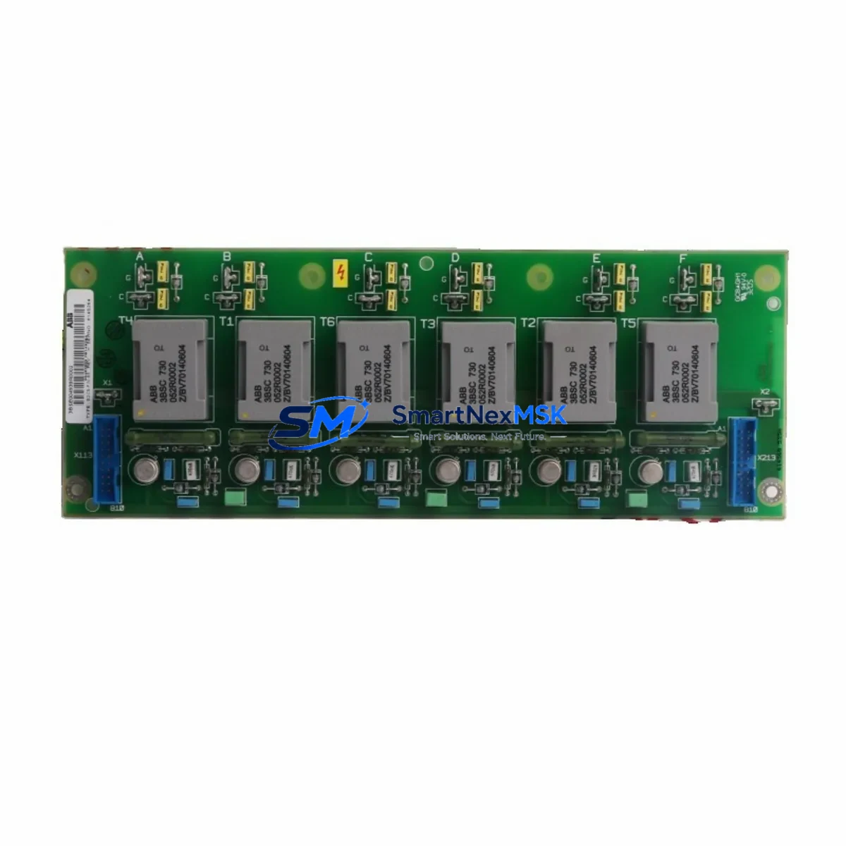
ABB 3BSE004939R2 Retrofit-Ready Gate Pulse Isolation Board for SDCS Control Systems
The ABB 3BSE004939R2 (SDCS-PIN-48) is a Gate Pulse Isolation Board engineered for ABB’s SDCS series DC drive platforms. As legacy DC drive installations age and original spare parts become increasingly scarce, this board serves as a verified retrofit-ready replacement that enables plant engineers to restore full drive functionality without redesigning the control architecture. Whether you are recovering from an unplanned drive failure, executing a planned control cabinet upgrade, or migrating from an end-of-life SDCS-CON-2 or SDCS-CON-3 controller assembly, the 3BSE004939R2 provides a direct-fit solution with minimal commissioning overhead.
The SDCS-PIN-48 interfaces directly with the SDCS-CON-4 control board and the SDCS-POW-1 power supply module, maintaining the original gate firing signal chain for the thyristor bridge. Before installation, engineers must verify the DC bus voltage rating, confirm that the existing SDCS-FEX-2 field excitation module is compatible with the replacement board’s signal levels, and check that the SDCS-DSL-4 serial link adapter is correctly addressed on the drive’s internal communication bus. Failure to validate these parameters before power-up can result in asymmetric firing pulses and premature thyristor failure.
During retrofit planning, the terminal block layout on the 3BSE004939R2 matches the original SDCS-PIN-48 pinout, which significantly reduces rewiring time. However, technicians should photograph and document all existing wiring connections before removal, particularly the gate and cathode leads routed to the thyristor stack. The board mounts on the standard SDCS backplane and does not require additional hardware modifications. If the existing backplane shows signs of corrosion or mechanical stress, it is advisable to replace it concurrently with the SDCS-PIN-48 to avoid intermittent contact faults after commissioning.
Upgrade Compatibility Table
| Parameter | Details |
|---|---|
| Part Number | 3BSE004939R2 / SDCS-PIN-48 |
| Compatible Platform | ABB SDCS DC Drive Series (SDCS-CON-2, SDCS-CON-3, SDCS-CON-4) |
| Interface | SDCS Backplane — direct plug-in, no adapter required |
| Communication Compatibility | Compatible with SDCS-DSL-4 serial link; supports DCS 400 / DCS 500 / DCS 600 drive families |
| Power Supply Requirement | Works with SDCS-POW-1 and SDCS-POW-4 power supply modules |
| Field Excitation | Compatible with SDCS-FEX-2 field excitation module |
| Installation Type | Direct replacement — same mounting footprint and terminal layout |
| Retrofit Recommendation | Suitable for DCS 400 / DCS 500 / DCS 600 legacy system upgrades |
| Commissioning Note | Verify gate pulse timing via DriveWindow or equivalent commissioning tool before full load test |
| Warranty | 12-Month Warranty — covers manufacturing defects and functional failure under normal operating conditions |
Retrofit Planning for Existing Automation Systems
A successful SDCS-PIN-48 retrofit begins well before the replacement board arrives on site. The first step is a full audit of the existing drive cabinet: confirm the firmware version loaded on the SDCS-CON-4 control board, check the parameter set stored in the drive’s non-volatile memory, and export a backup using DriveWindow or the SDCS-AMC-DC adapter before any hardware is disturbed. This parameter backup is critical — if the replacement board triggers a factory reset during initialization, the original motor tuning data, speed reference scaling, and torque limit settings must be restored from this backup to avoid a lengthy re-commissioning cycle.
The retrofit process also requires attention to the surrounding module ecosystem. The SDCS-POW-1 power supply module should be load-tested before the new gate pulse board is installed, as a marginal power supply can cause erratic firing behavior that is easily misdiagnosed as a board defect. Similarly, the SDCS-FEX-2 field excitation module should be inspected for capacitor aging, particularly in installations that have been in service for more than ten years. If the control cabinet also houses an ACS 600 or ACS 800 series AC drive sharing the same control bus, verify that the SDCS-DSL-4 serial link adapter addressing does not conflict after the replacement.
For plants running Profibus DP or Modbus RTU communication between the drive and the supervisory PLC, the communication link must be re-validated after the board swap. The SDCS-COM-8 Profibus adapter or SDCS-COM-81 Modbus module should be checked for correct node addressing and baud rate settings. HMI screens connected via the drive’s serial port — particularly older Panel Builder or InduSoft-based SCADA displays — may require a communication timeout adjustment if the new board’s initialization sequence is slightly longer than the original. This is a common oversight that causes nuisance communication fault alarms during the first power-up after retrofit.
I/O wiring connected to the SDCS-IOB-3 I/O extension board should also be verified for correct signal levels, especially analog speed reference inputs and digital run/stop commands routed from the plant’s safety relay circuit. All field wiring should be re-torqued to the terminal block specifications after the board replacement to prevent loose connections that can cause intermittent faults under vibration.
Downtime Control During System Migration
Minimizing production downtime during a DC drive board replacement requires a structured pre-outage preparation protocol. Before the scheduled maintenance window, the engineering team should complete the following: export and verify the full drive parameter set, prepare a wiring diagram cross-referenced to the existing terminal block labels, stage the replacement 3BSE004939R2 board in an ESD-safe environment, and confirm that all required tools — including a calibrated torque driver, oscilloscope for gate pulse verification, and a laptop with DriveWindow installed — are available at the work site.
During the outage, the recommended sequence is: isolate and lock out the drive’s AC input, discharge the DC bus capacitors fully before touching any internal components, remove the SDCS-PIN-48 by releasing the backplane connector latch, install the replacement board, and restore all gate and cathode wiring connections before re-energizing. A no-load test at reduced speed reference should be performed first to verify symmetrical gate firing before the drive is returned to full production load. This approach typically allows a complete board swap and functional verification to be completed within a two-to-four hour maintenance window, depending on cabinet accessibility and the complexity of the existing wiring.
Protecting the original program logic is equally important. The SDCS-CON-4 stores its parameter set in non-volatile memory, but a board replacement can occasionally trigger a parameter reset if the new board’s firmware version differs from the original. Always confirm the firmware version on the replacement board matches the existing control board before installation, or be prepared to reload the parameter backup immediately after first power-up. For plants where continuous process control is critical, consider staging a fully pre-configured spare drive assembly as a hot-swap unit to reduce the active outage window to under thirty minutes.
Retrofit Support FAQ
Q1: Is the ABB 3BSE004939R2 a direct drop-in replacement for the original SDCS-PIN-48?
Yes. The 3BSE004939R2 uses the same backplane connector, terminal block layout, and mounting footprint as the original SDCS-PIN-48. No mechanical modifications are required. However, always verify the firmware version on the SDCS-CON-4 control board is compatible with the replacement gate pulse board before installation.
Q2: What commissioning steps are required after installing the 3BSE004939R2?
After installation, perform a no-load power-up test and verify gate pulse symmetry using an oscilloscope or DriveWindow diagnostic tool. Reload the parameter backup if the drive has reset to factory defaults. Re-validate the Profibus or Modbus communication link if applicable, and confirm that all analog and digital I/O signals are functioning correctly before returning the drive to production load.
Q3: How do I confirm wiring compatibility before replacing the board?
Document all existing wiring connections with photographs before removal. Cross-reference the gate and cathode lead assignments against the SDCS-PIN-48 wiring diagram in the ABB DCS 400/500/600 hardware manual. Re-torque all terminal connections to the specified values after installation. If the existing wiring uses non-standard extensions or field modifications, consult the original commissioning records before proceeding.
Q4: What does the 12-month warranty cover?
All units are covered by a 12-month warranty from the date of shipment. The warranty covers manufacturing defects and functional failure under normal operating conditions. Each board undergoes pre-shipment functional testing before dispatch. Warranty claims are supported by our technical team — contact [email protected] with your order reference and a description of the fault for rapid resolution.
© 2026 SMARTNEXMSK. All rights reserved.
Original Source: https://smartnexmsk.com
Contact: [email protected] | +86 18259474341



