
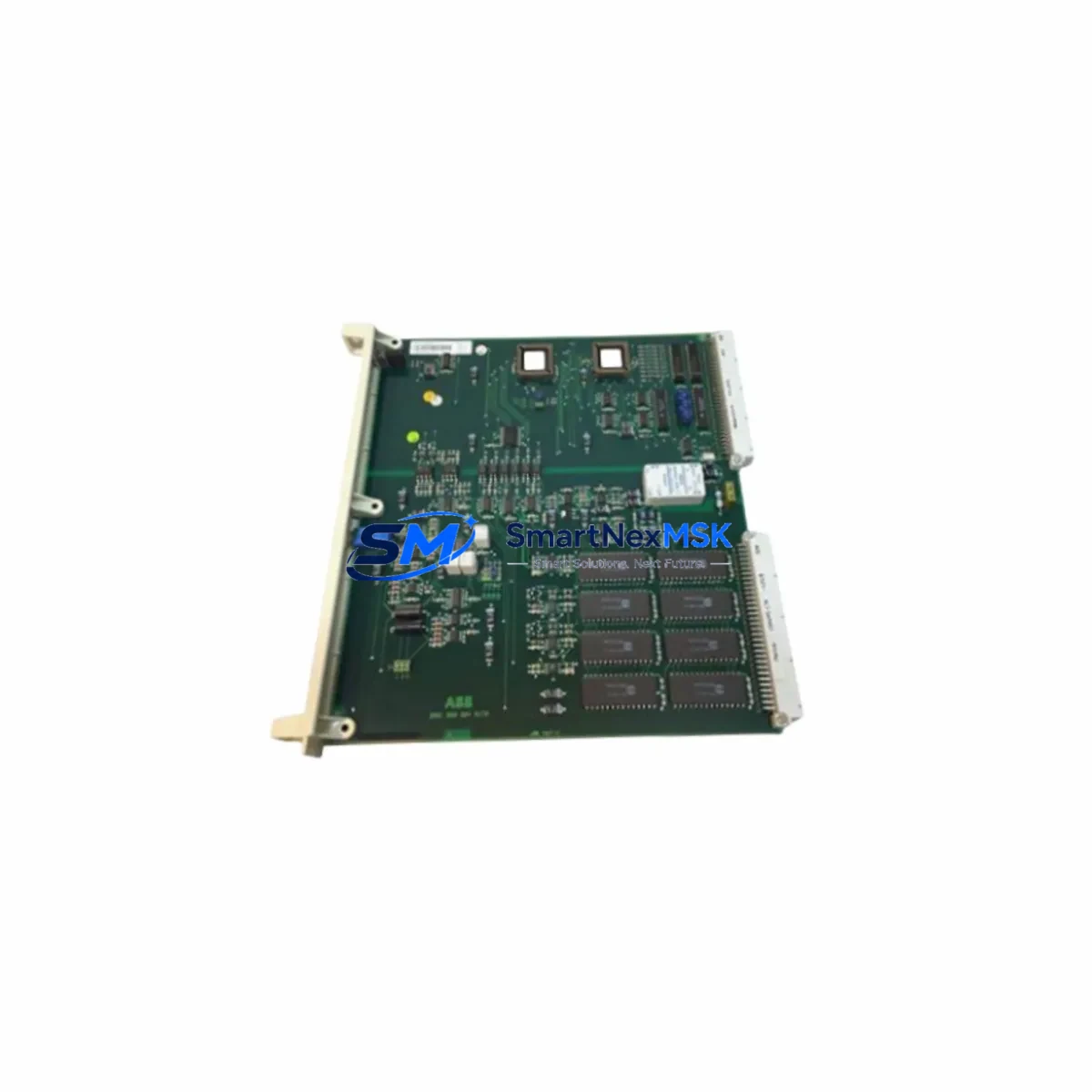
ABB 4006L4101AB G002 Retrofit-Ready Drive Control Board for ACS800 Control Systems
The ABB 4006L4101AB G002 (also referenced as 166C7875AA-0) is a retrofit-ready drive control board engineered for seamless integration into ABB ACS800 series variable frequency drives. As legacy ACS800 installations age and original spare parts become increasingly scarce, this board provides a verified drop-in replacement path that preserves existing wiring, terminal layouts, and drive firmware compatibility — minimizing engineering rework and unplanned downtime during system modernization projects.
Industrial facilities running ACS800 drives in motor control centers, pump stations, compressor lines, conveyor systems, and crane applications rely on the control board as the central processing unit for speed reference handling, fault diagnostics, I/O signal routing, and fieldbus communication. When the original control board fails or reaches end-of-life, replacing it with a functionally equivalent unit like the 4006L4101AB G002 allows maintenance teams to restore full drive operation without replacing the entire drive cabinet or rewriting application programs stored in the RDCU or RMIO control units.
Upgrade Compatibility Table
| Parameter | Details |
|---|---|
| Compatible Drive Series | ABB ACS800 (single drive and multidrive configurations) |
| Replaces / Cross-Reference | 4006L4101AB G002 / 166C7875AA-0 |
| Mounting Interface | Direct backplane slot mount; compatible with standard ACS800 control section chassis |
| Communication Compatibility | Supports RDCO-01/02/03 fieldbus adapter modules (PROFIBUS, DeviceNet, Modbus); compatible with DDCS fiber-optic links for multidrive systems |
| I/O Interface | Retains standard RMIO-11C / RMIO-12C terminal block pinout; no rewiring required for standard installations |
| Firmware / Parameter Compatibility | Compatible with ACS800 standard application program and system application program parameter sets; existing parameter backups can be restored via DriveWindow or DriveWindow Light |
| Replacement Recommendation | Suitable for direct swap in ACS800-01, ACS800-02, ACS800-04, ACS800-07, ACS800-11, ACS800-17 frame sizes |
| Commissioning Notes | Verify drive ID run after replacement; re-enter motor nameplate data if parameter memory is not retained |
| Warranty | 12-Month Warranty — covers manufacturing defects and functional failure under normal operating conditions |
Retrofit Planning for Existing Automation Systems
A successful ACS800 control board retrofit begins well before the replacement unit arrives on site. Engineers should first retrieve the existing parameter backup using DriveWindow Light connected via the RDCU panel link or USB-to-RS232 programming cable. This backup captures all application-specific tuning values, speed references, acceleration ramps, fault response settings, and I/O assignments that would otherwise need to be re-entered manually after the swap.
Next, verify the power supply section of the drive. The APBU-44C or APBU-12C pulse encoder interface board, if installed, must be checked for compatibility with the replacement control board revision. In multidrive systems using a common DC bus, the ACSM1 or ACS800-104 inverter modules share a DDCS fiber-optic ring with the control board — confirm that the fiber connections to the RDCO adapter are intact and that the node addresses are correctly set before powering up the replacement board.
Terminal block wiring on the RMIO control unit should be photographed and documented before removal. The standard 24 VDC auxiliary power input, analog input channels AI1/AI2, digital input channels DI1–DI6, relay outputs RO1–RO3, and the encoder feedback terminals should all be verified against the original wiring diagram. If the installation includes an RTAC-01 or RAIO-01 I/O extension module, confirm that the module address switches are set correctly to avoid address conflicts after the control board is replaced.
For facilities that have integrated the ACS800 into a PROFIBUS DP network via the RDCO-03 adapter, the GSD file and node address must be confirmed in the PLC configuration — typically a Siemens S7-300, S7-400, or equivalent controller managing the drive network. After the board swap, the PROFIBUS master should perform a full network scan to confirm the drive is recognized at the correct address before releasing the system to automatic mode.
HMI panels connected to the drive via the CDP312R panel bus or Modbus RTU link should be tested for communication continuity after the replacement. If the facility uses a Wonderware, FactoryTalk, or WinCC SCADA system with OPC DA/UA tags mapped to drive parameters, verify that all tag addresses remain valid after the parameter restore. The RDCU-12C remote I/O unit, if used for distributed I/O expansion, should also be power-cycled and confirmed online before returning the drive to service.
Downtime Control During System Migration
Minimizing production interruption during a control board replacement requires a structured pre-outage preparation protocol. Before the scheduled maintenance window, complete the parameter backup, prepare the replacement 4006L4101AB G002 board with an ESD-safe handling procedure, and stage all required tools including a torque screwdriver, fiber-optic cleaning kit, and a laptop loaded with DriveWindow Light.
During the outage, follow the ABB ACS800 hardware manual lockout/tagout procedure before opening the drive cabinet. Remove the RMIO control unit carefully, transfer the RDCO fieldbus adapter and any installed option modules to the replacement board, and reseat the unit in the control section chassis. Reconnect all fiber-optic DDCS cables and verify the panel link to the CDP312R or RDCU unit.
On power-up, the drive should perform a self-test sequence. Restore the parameter backup immediately and run the motor ID run if the drive controls a permanent magnet or high-efficiency induction motor. Confirm all digital inputs, analog references, and relay outputs are responding correctly before releasing the drive to the process control system. A structured commissioning checklist targeting under 90 minutes of total outage time is achievable for experienced maintenance teams familiar with the ACS800 platform.
All units are pre-tested and function-verified before shipment. Each 4006L4101AB G002 board is covered by a 12-month warranty against manufacturing defects and functional failure, providing confidence for both emergency replacements and planned retrofit projects.
Retrofit Support FAQ
Q1: Is the 4006L4101AB G002 a direct drop-in replacement for the original ABB ACS800 control board?
Yes. The 4006L4101AB G002 (cross-reference 166C7875AA-0) is designed as a functionally equivalent replacement for the original ACS800 drive control board. The backplane connector, terminal block layout, and option module slots are compatible with standard ACS800 control section chassis. No mechanical modifications are required for a standard swap.
Q2: Can I restore my existing parameter set after replacing the control board?
Yes, provided you have a parameter backup saved via DriveWindow or DriveWindow Light prior to the replacement. Connect the programming cable to the RDCU panel link port, open the backup file, and download the parameter set to the new board. Verify motor data parameters (Group 99) and perform a motor ID run if required by the application.
Q3: What fieldbus protocols are supported, and will my existing PROFIBUS or Modbus configuration still work?
The 4006L4101AB G002 supports all RDCO-series fieldbus adapter modules including RDCO-01 (DeviceNet), RDCO-02 (PROFIBUS DP), and RDCO-03 (PROFIBUS DP with extended diagnostics). Existing Modbus RTU configurations via the standard serial port are also retained. After the board swap, confirm the node address and baud rate settings match the original configuration before reconnecting to the PLC or SCADA network.
Q4: What does the 12-month warranty cover, and how is the unit tested before shipment?
Every 4006L4101AB G002 unit undergoes functional testing prior to shipment, including power-on self-test verification and I/O channel checks. The 12-month warranty covers manufacturing defects and functional failure under normal operating conditions from the date of receipt. Warranty claims are supported by our technical team at [email protected]. Units showing damage from incorrect installation, overvoltage, or ESD mishandling are not covered under the standard warranty terms.
© 2026 SMARTNEXMSK. All rights reserved.
Original Source: https://smartnexmsk.com
Contact: [email protected] | +86 18259474341



