
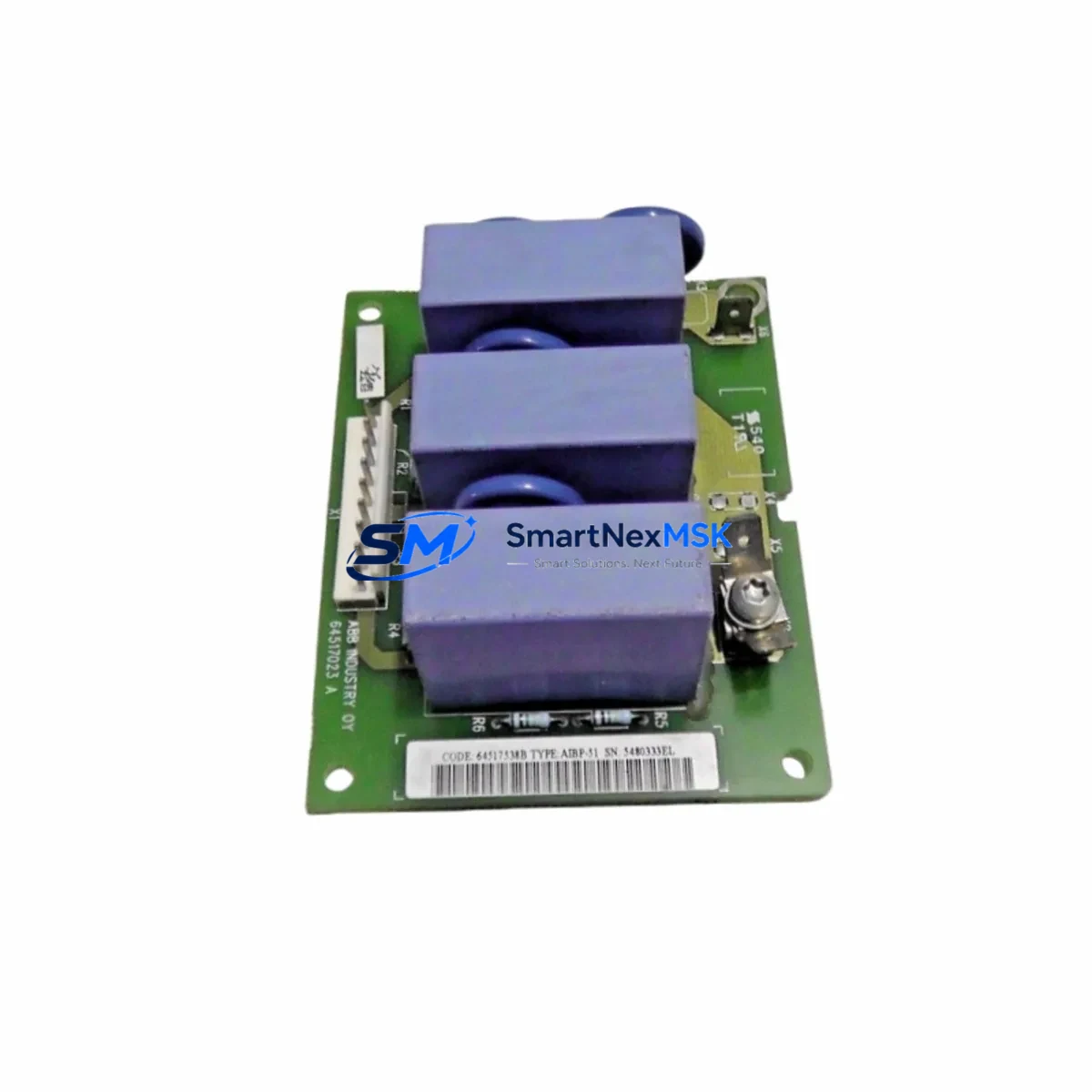
ABB AIBP-51 64517023A Spare for ACS Series Automation
The ABB AIBP-51 (part number 64517023A) is an original control interface board designed for ABB ACS Series variable frequency drives, including the ACS550, ACS580, and ACS800 platform families. In industrial maintenance environments, unplanned drive downtime can halt entire production lines within minutes. Stocking a verified replacement AIBP-51 board is a proven strategy for maintenance engineers who need to restore drive operation quickly without waiting for extended lead times from OEM channels.
This board serves as the primary I/O and fieldbus communication interface within the ACS drive control cabinet. It manages digital and analog signal routing between the drive’s main control unit and external automation systems, including PLC racks, DCS controllers, and SCADA terminals. When the AIBP-51 fails — typically presenting as loss of fieldbus communication, erratic I/O response, or drive fault codes related to the control board — replacement is the fastest path to restoring full system operation.
For procurement engineers managing spare parts inventories across multi-drive installations, the AIBP-51 64517023A is a high-priority stocking item. A single failed board can affect multiple coordinated drive axes if the control architecture relies on shared communication backbones. Maintaining at least one verified spare per site significantly reduces mean time to repair (MTTR).
All units supplied by SMARTNEXMSK are sourced from authorized distribution channels, individually tested prior to shipment, and covered by a 12-month warranty against manufacturing defects and functional failure.
Spare Maintenance Table
| Parameter | Specification |
|---|---|
| Part Number | AIBP-51 / 64517023A |
| Brand | ABB |
| Compatible Series | ACS550, ACS580, ACS800 |
| Module Type | Drive Control Interface / I/O Board |
| Communication Interface | Fieldbus (PROFIBUS / Modbus RTU depending on firmware) |
| Mounting | Internal drive control slot, DIN-compatible bracket |
| Operating Temperature | 0°C to +55°C (standard industrial environment) |
| Origin | Finland (ABB OEM) |
| Condition | Original, new or tested-serviceable |
| Pre-shipment Test | Functional verification performed before dispatch |
| Warranty | 12 Months from date of shipment |
| Delivery | Global shipping, DHL / FedEx / UPS available |
Maintenance Planning for Continuous Operation
When replacing the AIBP-51 64517023A in the field, a thorough inspection of the surrounding control cabinet components is essential to prevent repeat failures and confirm system integrity. Maintenance engineers should begin by verifying the 24VDC auxiliary power supply feeding the control board — a degraded SDCS-POW-1 or equivalent ABB power supply module can cause intermittent board resets that mimic a faulty AIBP-51. Check supply voltage under load before installing the replacement board.
Next, inspect the RMIO or RDCO communication option boards installed in adjacent slots. These modules handle DDCS fiber-optic communication and are often stressed by the same electrical events that damage the AIBP-51. If the drive experienced a surge or ground fault event, the RDCO-02 or RDCO-03 fiber interface board should be tested independently before the system is returned to service.
Terminal block wiring on the X1 and X2 I/O connectors should be checked for loose terminations, oxidation, or insulation damage. In high-vibration environments, screw-type terminals on the AIBP-51’s analog input and digital output rows are a common source of intermittent signal faults. Re-torque all terminals to specification and inspect for signs of thermal stress.
For sites running PROFIBUS DP networks, verify the bus termination resistors at both ends of the segment after board replacement. A missing or failed termination on the PROFIBUS cable — often a 9-pin D-sub connector at the last node — can cause communication errors that appear to originate from the new board. Similarly, check the PBAI-01 or FPBA-01 PROFIBUS adapter if installed, as these modules interact directly with the AIBP-51’s communication layer.
Signal isolators on 4–20mA analog loops connected to the AIBP-51’s AI1 and AI2 inputs should be verified for correct output range. A failed isolator can inject out-of-range signals that trigger drive protection faults immediately after startup. Fuse holders on the 24VDC control circuit — typically 2A slow-blow — should also be inspected and replaced as a precaution during any board-level maintenance event.
For installations using ABB Panel Bus or Modbus RTU via the AIBP-51’s RS-485 port, confirm that the HMI terminal (such as an ACS-CP-C or ACS-CP-D control panel) is communicating correctly after replacement. Panel communication loss is a common post-replacement symptom caused by incorrect node address settings on the new board.
Site Replacement Workflow
Step 1 — Isolation: De-energize the ACS drive fully. Confirm zero voltage on DC bus capacitors using a calibrated multimeter before opening the control section. Allow minimum 5 minutes discharge time after main power removal.
Step 2 — Documentation: Photograph all wiring connections on the AIBP-51’s I/O terminals and note the DIP switch and parameter settings visible on the existing board. Record the drive’s parameter backup if the ACS control panel supports parameter upload.
Step 3 — Board Removal: Disconnect all ribbon cables and I/O terminal blocks from the AIBP-51. Remove the board retaining screws and extract the module from the control slot. Handle by edges only — ESD precautions apply.
Step 4 — Replacement Installation: Insert the new AIBP-51 64517023A into the control slot. Reconnect all terminal blocks and ribbon cables in reverse order. Confirm DIP switch settings match the documented configuration of the removed board.
Step 5 — Power-Up and Verification: Restore auxiliary 24VDC power first. Confirm the control panel displays correctly and no fault codes are active. Restore main power and run the drive at low speed to verify I/O response and fieldbus communication before returning to full production load.
This workflow supports direct replacement of legacy AIBP-51 variants across ACS550 and ACS800 installations without requiring drive re-commissioning, provided parameter settings are preserved. Compatibility with older firmware revisions should be confirmed with the part number suffix before installation.
Spare Parts Support FAQ
Q: Is the AIBP-51 64517023A compatible with all ACS Series drive variants?
A: The AIBP-51 64517023A is designed for the ACS550, ACS580, and ACS800 series. Compatibility with specific firmware versions and hardware revisions should be confirmed using the drive’s nameplate data and the ABB hardware compatibility matrix. Contact our technical team with your drive serial number for pre-purchase verification.
Q: What pre-shipment testing is performed on each unit?
A: Every AIBP-51 unit is functionally tested prior to dispatch, including power-on verification, I/O channel continuity, and communication port integrity checks. A test report is available upon request. Units are packed in anti-static ESD bags with protective foam inserts.
Q: What is the warranty coverage and claim process?
A: All units carry a 12-month warranty from the date of shipment. Warranty covers functional failure under normal operating conditions. To initiate a claim, contact [email protected] with the order number, installation date, and a description of the fault. Replacement or refund is processed within 5 business days of fault confirmation.
Q: Can SMARTNEXMSK support long-term supply for multi-site maintenance contracts?
A: Yes. We maintain buffer stock of high-demand ABB ACS Series spare parts including the AIBP-51, RDCO-02, SDCS-POW-1, and related control modules. Framework agreements with fixed pricing and reserved inventory allocation are available for maintenance contractors and plant operators managing multiple drive installations.
© 2026 SMARTNEXMSK. All rights reserved.
Original Source: https://smartnexmsk.com
Contact: [email protected] | +86 18259474341



