
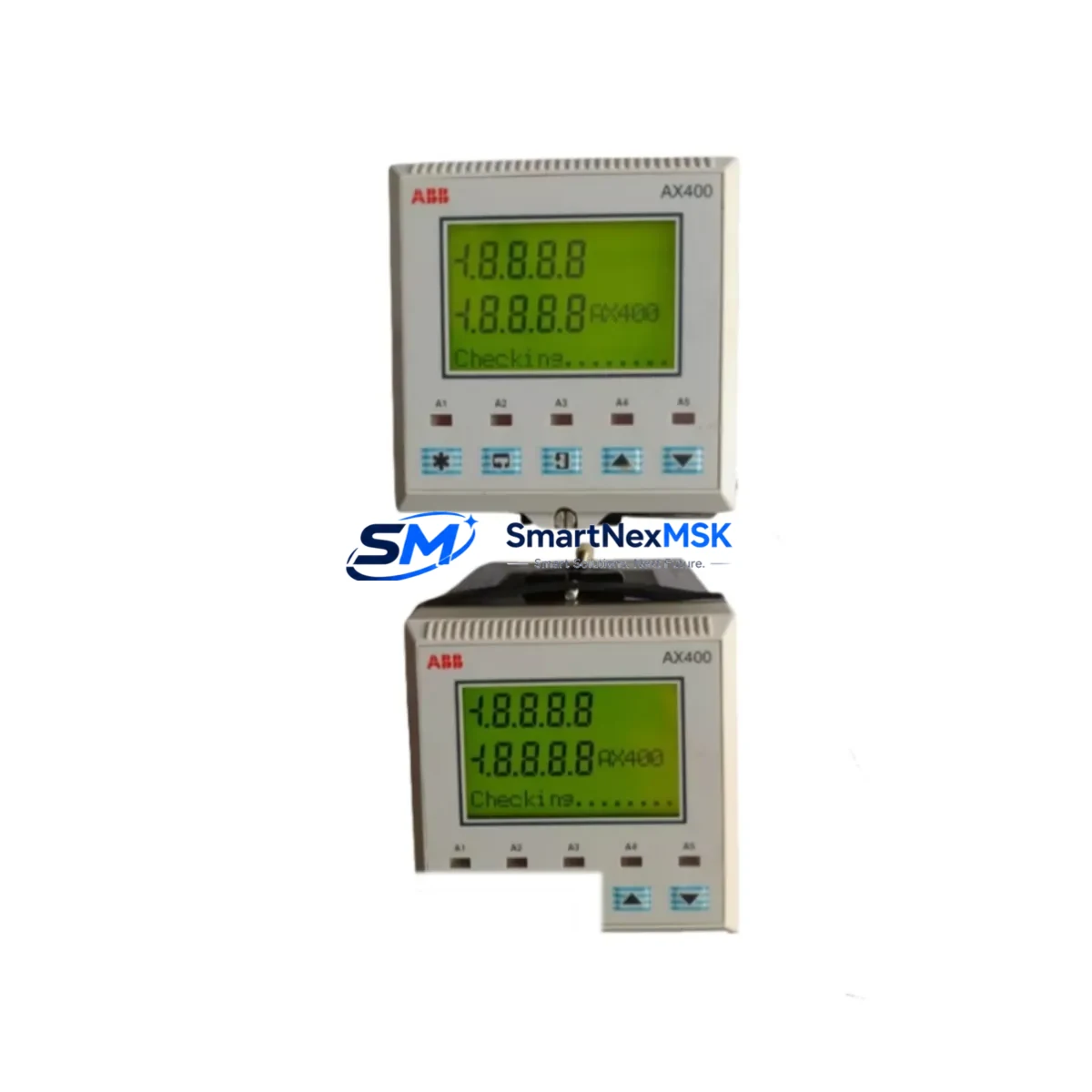
ABB AX552 Maintenance-Ready Spare for AC500 Automation
The ABB AX552 is an original analog I/O expansion module designed for the ABB AC500 PLC series — one of the most widely deployed programmable logic controller platforms in industrial process control, machine automation, and infrastructure applications. Sourced as a genuine OEM spare, the AX552 is stocked and tested to support maintenance engineers who require a verified, drop-in replacement that eliminates configuration risk and minimizes unplanned downtime.
In industrial environments where control system uptime is directly tied to production output, having a pre-qualified spare on the shelf is not optional — it is a maintenance discipline. The AX552 module handles analog signal acquisition and output within the AC500 I/O bus, making it a critical node in any loop involving temperature, pressure, flow, or position feedback. A failed or degraded AX552 can disrupt entire process segments, trigger safety shutdowns, or cause erratic PID behavior that is difficult to diagnose without a known-good replacement available for swap testing.
This listing is intended for maintenance engineers, reliability teams, and procurement engineers managing spare parts inventories for AC500-based control systems. Every unit is inspected prior to dispatch, ships with full documentation, and is covered by a 12-month warranty.
Spare Maintenance Table
| Parameter | Specification |
|---|---|
| Part Number / SKU | AX552 |
| Brand | ABB |
| Series | AC500 |
| Module Type | Analog I/O Expansion Module |
| Analog Inputs | 4 × configurable (voltage / current) |
| Analog Outputs | 2 × configurable (voltage / current) |
| Signal Range | 0–10 V / 0–20 mA / 4–20 mA |
| Resolution | 12-bit |
| Supply Voltage | 24 V DC (via I/O bus) |
| Operating Temperature | -25 °C to +60 °C |
| Mounting | DIN rail, AC500 I/O bus connector |
| Country of Origin | Germany |
| Compatibility | AC500 CPU modules: PM554, PM564, PM572, PM581, PM582, PM591, PM592 |
| Certifications | CE, UL (series-level) |
| Weight | 126 g |
| Warranty | 12 Months — covers manufacturing defects and functional failure under normal operating conditions |
| Condition | Original / New |
| Shipping | Tested before dispatch; worldwide delivery available |
Maintenance Planning for Continuous Operation
When replacing or inspecting an AX552 module in the field, a disciplined maintenance engineer will not stop at the module itself. The AX552 sits within a broader electrical and signal chain, and a failure in any adjacent component can cause symptoms that mimic a faulty analog module — or cause a new AX552 to fail prematurely if the root cause is not addressed.
Begin with the AC500 CPU module (such as the PM564 or PM572) to confirm that the I/O bus is healthy and that the CPU is correctly enumerating the AX552 after replacement. Check the TB521 or TB541 terminal base that the AX552 plugs into — worn or corroded bus contacts are a common cause of intermittent analog faults that are incorrectly attributed to the module itself.
Inspect the 24 V DC power supply feeding the I/O bus. Ripple, voltage sag under load, or inadequate current capacity can corrupt analog readings and cause the AX552 to report out-of-range values. A dedicated CP502 or CP504 power supply module from the AC500 family should be verified for output stability before commissioning the replacement AX552.
For signal integrity, review the field wiring connected to the AX552’s analog input terminals. Shielded cable continuity, proper grounding at a single point, and correct termination resistance are all factors that affect 4–20 mA loop accuracy. If the system uses signal isolators or loop-powered transmitters, verify that these are functioning correctly — a failed isolator can present as an AX552 input fault.
In control cabinets where the AX552 is part of a larger AC500 rack, also inspect the DC532 or DC522 digital I/O modules in adjacent slots for signs of thermal stress or connector wear. Check the CM572-DP or CM589-PNIO communication modules if the system uses PROFIBUS or PROFINET — a communication fault can prevent the CPU from reading analog values even when the AX552 hardware is fully functional.
Finally, review the fuse protection on the 24 V supply rail and any surge protection devices on analog input lines. In environments with variable-speed drives, welding equipment, or high-inductive loads, transient protection is essential to extend the service life of analog modules.
Site Replacement Workflow
Step 1 — Preparation: Before removing the existing AX552, export the current AC500 project from Automation Builder or PS501 Control Builder Plus and note the module address and I/O configuration. Confirm the replacement AX552 SKU matches the installed unit — do not substitute with AX521 or AX561 without verifying channel count and signal range compatibility.
Step 2 — Safe Isolation: De-energize the I/O bus segment. The AC500 supports hot-swap on select CPU variants, but analog modules should be replaced with the bus powered down where possible to avoid transient signals reaching field instruments.
Step 3 — Physical Replacement: Slide the AX552 off the terminal base. Inspect the bus connector pins on both the module and the TB base for damage. Seat the new AX552 firmly until the locking tab engages.
Step 4 — Re-energize and Verify: Power up the I/O bus. The CPU should automatically recognize the AX552 at its configured address. Verify analog input readings against known reference signals (e.g., a calibrated 4–20 mA source) before returning the loop to automatic control.
Step 5 — Documentation: Record the replacement in the maintenance log with date, technician, and the serial number of the removed module. Retain the old module for failure analysis if the fault cause has not been confirmed.
Spare Parts Support FAQ
Q1: Is this AX552 an original ABB part or a compatible substitute?
This is an original ABB AX552 module — not a clone, compatible, or refurbished unit. It is sourced from authorized supply channels and is functionally identical to the module installed in your AC500 system at the factory.
Q2: What does the 12-month warranty cover?
The warranty covers manufacturing defects and functional failure under normal operating conditions for 12 months from the date of dispatch. Units that fail due to incorrect installation, overvoltage, or physical damage are not covered, but our technical team will assist with failure analysis at no charge.
Q3: How do I confirm compatibility with my specific AC500 CPU?
The AX552 is compatible with all AC500 V2 and V3 CPU modules including the PM554, PM564, PM572, PM581, PM582, PM591, and PM592. If you are running an older AC500 V1 system, please contact us with your CPU part number before ordering to confirm bus compatibility.
Q4: What pre-shipment testing is performed?
Each AX552 unit is powered and functionally tested on an AC500 test bench prior to dispatch. Analog input and output channels are verified against specification limits. A test report is available on request for critical maintenance applications.
© 2026 SMARTNEXMSK. All rights reserved.
Original Source: https://smartnexmsk.com
Contact: [email protected] | +86 18259474341



