
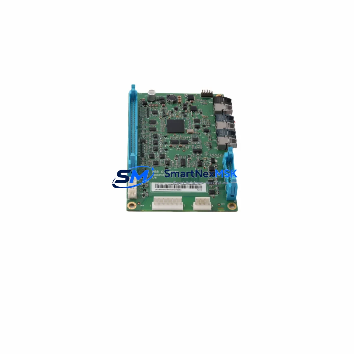
ABB BINT-12C Retrofit-Ready Drive Interface for BINT Series: Compatible Modernization and Smooth Legacy System Upgrade
The ABB BINT-12C is a drive interface board engineered for fieldbus communication integration within ABB’s BINT Series drive platforms, including the widely deployed ACS600 and ACS800 variable frequency drive families. As legacy control architectures age and OEM support for discontinued modules becomes increasingly limited, the BINT-12C has emerged as a critical retrofit component for engineers tasked with modernizing existing automation infrastructure without full system replacement. Whether you are managing a planned upgrade cycle or responding to an unplanned failure on a production line, the BINT-12C provides a verified, drop-in compatible solution that preserves your existing drive investment while restoring full communication and control capability.
Sourced directly from authorized distribution channels and subjected to pre-shipment functional testing, each BINT-12C unit shipped by SMARTNEXMSK is backed by a 12-month warranty covering manufacturing defects and operational failures under normal industrial service conditions. Our inventory is maintained to support urgent replacement requirements, with same-day dispatch available for in-stock units and expedited logistics options for critical downtime situations.
Upgrade Compatibility Table
| Parameter | Details |
|---|---|
| Compatible Drive Series | ABB ACS600, ACS800, ACS550 (with adapter slot) |
| Module Slot Interface | Standard BINT Series option slot; direct backplane insertion |
| Communication Protocol Support | Profibus-DP, DeviceNet, Modbus RTU (protocol-dependent on paired adapter) |
| Replacement Compatibility | Direct replacement for BINT-11C, BINT-12C legacy units; verify firmware revision before swap |
| Installation Requirement | Drive must be powered down; ESD precautions required; re-parameterization via DriveWindow or ACS panel |
| Commissioning Requirement | Parameter group 51 (Ext Comm Module) must be reconfigured post-installation |
| Debugging Focus | Node address setting, baud rate alignment, PLC I/O mapping verification |
| Warranty | 12 months from date of shipment; covers manufacturing defects under normal operating conditions |
Retrofit Planning for Existing Automation Systems
Successful integration of the BINT-12C into a legacy control environment requires a structured pre-installation assessment. Engineers should begin by auditing the existing drive cabinet to confirm the available option slot type and verify that the host drive’s firmware version is compatible with the BINT-12C’s communication stack. In ACS800 installations, the drive’s parameter set — particularly parameter groups 10, 51, and 98 — must be reviewed and backed up using DriveWindow Light or an equivalent configuration tool before any hardware is disturbed.
Power supply capacity within the control cabinet is a frequent oversight during retrofit projects. The BINT-12C draws its operating power from the drive’s internal 24 VDC auxiliary supply via the option slot backplane. If the existing SDCS-CON-4 control board or equivalent is already supporting multiple option modules — such as an RDCO-03 DDCS fiber optic communication module or an RETA-01 Ethernet adapter — the total current budget must be recalculated to confirm headroom for the BINT-12C without triggering undervoltage faults on the auxiliary rail.
Terminal wiring adaptation is another key consideration. In older ACS600 installations where the original fieldbus interface was handled by a NINT-41 or NINT-43 module, the physical connector pinout and cable shield grounding scheme may differ from the BINT-12C’s terminal arrangement. A wiring diagram comparison should be completed before disconnecting the existing fieldbus cable, and the cable shield should be re-terminated at the drive cabinet’s PE bar in accordance with ABB’s EMC installation guidelines to prevent communication noise after commissioning.
For systems using a PROFIBUS segment, the BINT-12C’s node address must be set to match the address previously assigned to the replaced module in the PLC’s hardware configuration — typically managed through Siemens STEP 7 or TIA Portal for installations where the drive is integrated into a Simatic S7-300 or S7-400 control network. After physical installation, the PLC’s GSD file for the drive should be verified against the BINT-12C’s supported I/O data format to ensure that the process data word mapping (speed reference, torque reference, status word, actual value) remains consistent with the existing ladder logic or function block diagram.
In multi-drive panel configurations — particularly those using an NDBU-95 DDCS branching unit to daisy-chain multiple ACS800 drives on a single fiber optic ring — the BINT-12C’s DDCS node address and optical power budget must be confirmed before the system is returned to service. The branching unit’s port assignments and the master drive’s DDCS configuration parameters should be documented and cross-checked after the module swap to prevent address conflicts that could cause the entire drive network to fault on startup.
HMI screen updates are often overlooked during drive interface retrofits. If the existing operator panel — such as an ABB CDP312R or a third-party panel PC running InTouch or iFIX — displays drive status data sourced from the fieldbus, the data block addresses and variable tags must be verified against the BINT-12C’s actual process data output after commissioning. Any discrepancy in the status word bit mapping between the old and new module versions can cause misleading fault indications on the HMI, which may delay production restart.
Downtime Control During System Migration
Minimizing unplanned downtime during a drive interface board replacement requires preparation that begins well before the maintenance window opens. The most effective approach is to pre-configure the replacement BINT-12C off-line using a bench test setup — ideally a spare ACS800 or ACS600 drive of the same model — so that the module’s node address, baud rate, and parameter group settings are verified before it enters the production environment. This eliminates the most common cause of extended downtime: discovering a configuration mismatch only after the production drive has been reassembled and powered up.
A full parameter backup of the host drive should be completed using DriveWindow or the drive’s memory unit (such as the MFDT-01 flash memory module) before the BINT-12C is removed. This backup protects the motor control parameters, speed reference scaling, and application macro settings that would otherwise need to be re-entered manually if the drive loses its parameter set during the module exchange. In ACS800 systems with an active application program loaded via the RMIO board, the application program file should also be archived separately.
During the physical swap, the drive must be fully de-energized and the DC bus voltage verified to be below 50 VDC before the option slot cover is removed. The BINT-12C should be seated firmly into the backplane connector and secured with the retaining screw before power is restored. After power-up, the drive’s fault log should be cleared and the communication status LED on the BINT-12C observed during the first PLC scan cycle to confirm that the fieldbus link is established before the drive is released for production operation.
For critical continuous-process applications where even a brief interruption is unacceptable, a parallel commissioning strategy — where the replacement BINT-12C is installed in a standby drive that is brought online before the primary drive is taken offline — can reduce the effective process interruption to the duration of a controlled drive changeover, typically under two minutes in well-prepared installations.
Retrofit Support FAQ
Q1: Is the BINT-12C a direct drop-in replacement for the BINT-11C?
The BINT-12C and BINT-11C share the same physical form factor and backplane connector, making the BINT-12C a mechanically compatible replacement in most BINT Series option slots. However, firmware-level differences between revisions may require a parameter group 51 reconfiguration after installation. Always compare the firmware version of the host drive against ABB’s compatibility matrix before ordering, and confirm that the communication protocol adapter (e.g., RPBA-01 for PROFIBUS or RCAN-01 for CANopen) is compatible with the BINT-12C’s interface specification.
Q2: What pre-shipment testing is performed on each BINT-12C unit?
Each BINT-12C unit dispatched by SMARTNEXMSK undergoes a functional power-on test to verify that the module initializes correctly and that the backplane interface and communication status indicators operate within specification. Units that fail any stage of the test process are quarantined and not shipped. The 12-month warranty covers failures attributable to manufacturing defects or component quality issues that manifest under normal industrial operating conditions.
Q3: How do I verify fieldbus communication after installing the BINT-12C?
After installation and power-up, navigate to the drive’s parameter group 51 and confirm that parameter 51.01 (Ext1 Commands) is set to the correct fieldbus source. Monitor the drive’s fieldbus status word via the CDP312R operator panel or DriveWindow to confirm that the PLC is receiving a valid status word from the drive. On the PLC side, check the diagnostic buffer in STEP 7 or TIA Portal for any DP slave communication errors. If the PROFIBUS LED on the BINT-12C is flashing rather than steady, the most common causes are a node address mismatch, a baud rate detection failure, or a missing termination resistor at the end of the PROFIBUS segment.
Q4: What is covered under the 12-month warranty, and how is a warranty claim initiated?
The 12-month warranty covers manufacturing defects, component failures, and functional faults that occur under normal operating conditions within the rated environmental and electrical specifications of the BINT-12C. It does not cover damage resulting from incorrect installation, overvoltage events, ESD damage, or operation outside the module’s rated temperature and humidity range. To initiate a warranty claim, contact SMARTNEXMSK at [email protected] with the order reference number, a description of the fault symptom, and the drive fault log if available. Replacement units are dispatched upon fault confirmation, with return shipping of the defective unit required within 30 days.
© 2026 SMARTNEXMSK. All rights reserved.
Original Source: https://smartnexmsk.com
Contact: [email protected] | +86 18259474341



