
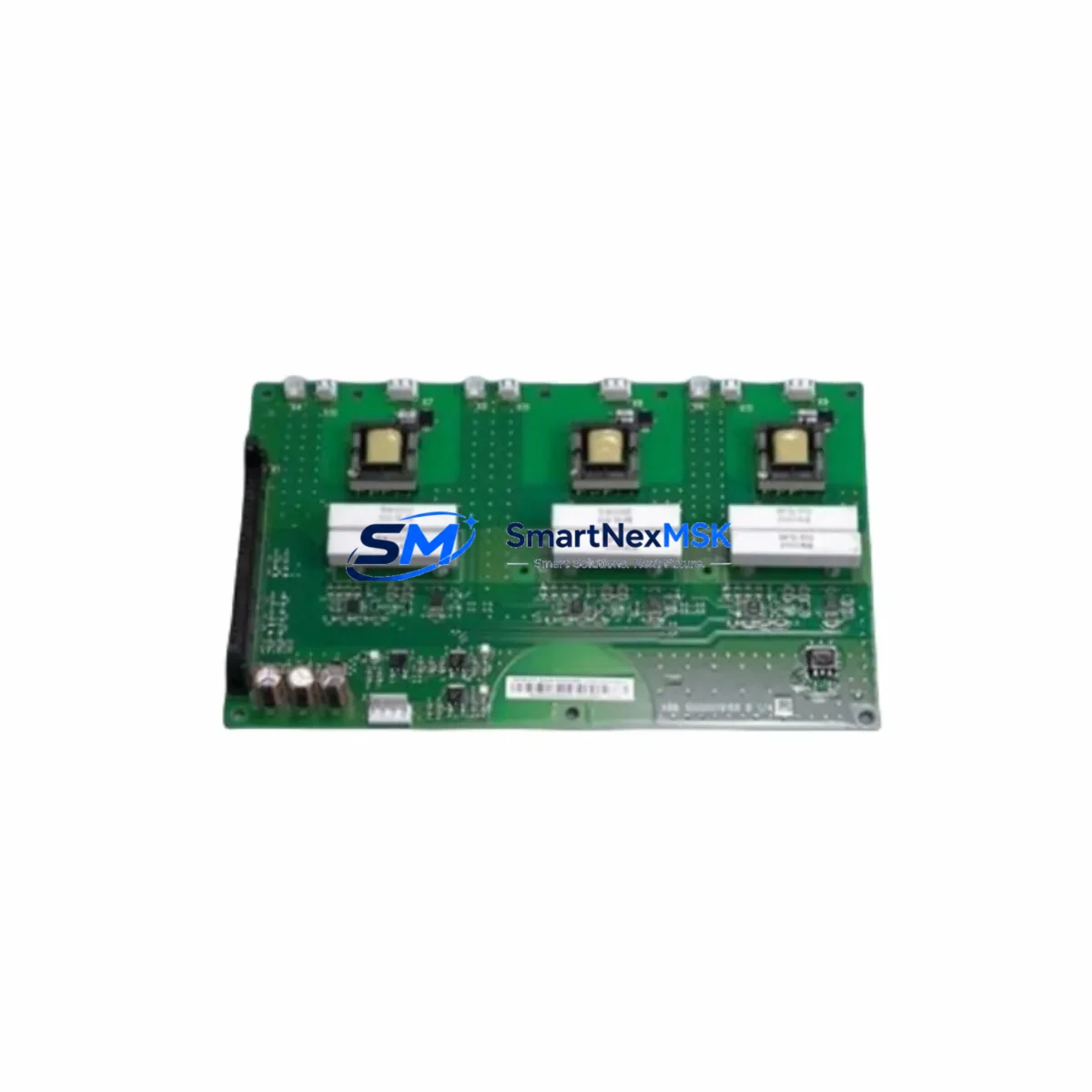
ABB BTDR-01C 3AUA0000094845 Retrofit-Ready MD Control Board for ACS800 Control Systems
The ABB BTDR-01C (part number 3AUA0000094845) is a Motor Drive Control Board engineered for direct retrofit and drop-in replacement within the ACS800 series variable frequency drive platform. As legacy ACS800 installations age out of OEM support cycles, procurement teams and automation engineers increasingly rely on verified aftermarket and surplus-stock boards like the BTDR-01C to restore drive functionality without committing to a full drive replacement. This board addresses the most common failure modes in ACS800 control sections — including gate driver faults, IGBT firing signal loss, and control logic corruption — while maintaining full compatibility with the existing drive cabinet, power section, and field wiring.
Whether you are managing a planned upgrade of an aging production line or responding to an unplanned drive fault in a critical process, the BTDR-01C provides a cost-effective, field-proven path to restoring control continuity. Each unit is sourced from verified supply channels, functionally tested prior to shipment, and backed by a 12-month warranty covering manufacturing defects and component failures under normal operating conditions.
Upgrade Compatibility Table
| Parameter | Details |
|---|---|
| Compatible Drive Series | ABB ACS800 (all frame sizes using BTDR-01C control board) |
| Part Number | BTDR-01C / 3AUA0000094845 |
| Board Function | MD (Motor Drive) Control Board — gate signal generation, fault logic, I/O interface |
| Backplane Interface | Direct plug-in to ACS800 control section backplane; no adapter required |
| Communication Compatibility | Compatible with RDCO-01/02/03 DDCS fiber optic adapters; supports PROFIBUS, DeviceNet, and Modbus RTU fieldbus modules mounted on the drive |
| I/O Compatibility | Retains existing analog and digital I/O terminal mapping; no rewiring required for standard configurations |
| Installation Requirement | ESD precautions required; power section must be fully de-energized and DC bus discharged before board swap |
| Parameter Restore | Backup existing parameters via DriveWindow or ACS800 control panel (ACS-CP-C or ACS-CP-D) before replacement |
| Retrofit Recommendation | Recommended for ACS800 units with control board faults, gate driver errors, or units where the original board is discontinued or unavailable |
| Commissioning Notes | Re-run motor ID run (Standard/Reduced) after board replacement; verify encoder feedback if RTAC-01 or RTAC-02 encoder interface module is installed |
| Warranty | 12 months from date of shipment — covers manufacturing defects and component failure under normal operating conditions |
Retrofit Planning for Existing Automation Systems
Successful retrofit of the BTDR-01C into an existing ACS800 installation requires systematic pre-work across several engineering disciplines. Before initiating the board swap, engineers should confirm the drive’s current firmware version using the ACS-CP-C or ACS-CP-D control panel, and export a full parameter backup via DriveWindow Light or DriveWindow 2. This backup is critical — the BTDR-01C ships without pre-loaded application parameters, and restoring the original parameter set is the fastest path to returning the drive to its previous operating state.
In multi-drive systems where the ACS800 is connected to an RDCO-03 DDCS fiber optic communication adapter for master-follower or drive-to-drive synchronization, the communication link topology should be documented before disassembly. The RDCO-03 mounts directly to the control board, and its fiber connections to adjacent drives or to an AC800M controller must be re-established in the correct sequence during recommissioning. Similarly, if the installation includes an RETA-01 Ethernet adapter or an RPBA-01 PROFIBUS adapter for integration with a DCS or SCADA system, these fieldbus modules should be removed carefully and reinstalled on the replacement board, with fieldbus node addresses and baud rate settings verified against the original configuration.
For installations where the ACS800 drives a motor with encoder feedback — common in winding, positioning, and tension control applications — the RTAC-01 or RTAC-02 pulse encoder interface module must be re-seated and its configuration parameters (encoder pulses per revolution, feedback channel selection) re-entered or restored from backup. Failure to verify encoder feedback configuration is one of the most common causes of post-retrofit commissioning delays.
In cabinet-level retrofit projects involving multiple ACS800 units, it is advisable to stage the board replacements one drive at a time, keeping the remaining drives operational to maintain partial production throughput. The APBU-44C or APBU-12C branching unit, if present in a multi-drive common DC bus configuration, should be inspected for bus voltage balance before and after each board swap. Power supply modules such as the SPSU-01 or SPSU-21 internal power supply board should also be checked for output voltage stability, as a degraded power supply can cause repeated control board failures and mask the true root cause of the original fault.
Terminal block wiring on the X1 and X2 control terminal strips of the ACS800 should be photographed and documented before removal. Standard analog input (AI1, AI2), digital input (DI1–DI6), relay output (RO1–RO3), and analog output (AO1) assignments are preserved across BTDR-01C replacements, but any custom wiring modifications made during the original installation must be re-verified against the site-specific wiring diagram.
Downtime Control During System Migration
Minimizing unplanned downtime during an ACS800 control board replacement requires preparation that begins well before the maintenance window opens. The most effective approach is to pre-stage the replacement BTDR-01C board alongside a printed copy of the drive’s parameter list, the site wiring diagram, and the ACS800 hardware manual. With these materials on hand, an experienced technician can complete the physical board swap in under 30 minutes.
Parameter restoration is the most time-sensitive step. If a DriveWindow backup file is available, restoration via the RS-232 or USB-to-RS-232 programming cable takes approximately 5–10 minutes. If no backup exists, parameters must be re-entered manually from the control panel — a process that can extend the commissioning window significantly for drives with complex application configurations. For this reason, SMARTNEXMSK recommends maintaining a current parameter backup for every ACS800 in service, stored both locally and in a centralized document management system.
After parameter restoration, the motor identification run (ID run) should be performed before returning the drive to automatic control. For drives in speed-critical or torque-critical applications, the Reduced ID Run is preferred to minimize mechanical stress during commissioning. Once the ID run completes successfully, verify the drive’s response to start/stop commands from the control system — whether via hardwired digital inputs, fieldbus command word, or HMI panel — before releasing the drive to production. If the installation uses an ABB Panel Bus or an ACS-CP-C remote panel, confirm that the panel communication link is active and that the drive status is correctly reflected on any connected HMI screens before closing the maintenance work order.
Retrofit Support FAQ
Q: Is the BTDR-01C 3AUA0000094845 a direct replacement for the original ABB ACS800 control board?
A: Yes. The BTDR-01C is a direct plug-in replacement for the MD control board position in ACS800 drives that originally used this part number. No mechanical modifications or adapter brackets are required. The board interfaces directly with the ACS800 backplane and retains the same terminal and connector layout as the original.
Q: Do I need to re-enter all drive parameters after replacing the BTDR-01C?
A: The replacement board ships without pre-loaded application parameters. If you have a DriveWindow parameter backup file, parameters can be restored in minutes via the RS-232 programming cable. If no backup is available, parameters must be re-entered manually. We strongly recommend creating and storing a parameter backup before initiating any board replacement.
Q: What pre-shipment testing is performed on the BTDR-01C?
A: Each BTDR-01C unit undergoes functional verification prior to shipment, including power-on testing and gate signal output checks. Units are inspected for physical damage, component integrity, and connector condition. All units are shipped with ESD-protective packaging. The 12-month warranty covers manufacturing defects and component failures under normal operating conditions from the date of shipment.
Q: What should I verify if the drive faults immediately after installing the replacement BTDR-01C?
A: First, confirm that the DC bus was fully discharged before installation and that all connectors are fully seated. Check that the parameter set has been correctly restored and that the motor ID run has been completed. If the drive is connected to an RDCO-03 fiber optic adapter or an RPBA-01 PROFIBUS module, verify that fieldbus communication is active and that the node address matches the system configuration. If faults persist, contact our technical support team with the fault code and drive nameplate data for further diagnosis.
© 2026 SMARTNEXMSK. All rights reserved.
Original Source: https://smartnexmsk.com
Contact: [email protected] | +86 18259474341



