
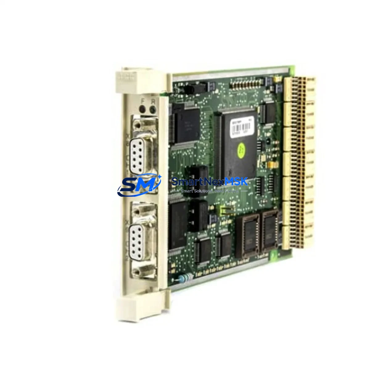
ABB CI520V1 3BSE012869R1 Retrofit-Ready AF100 Interface: Compatible Modernization for AC500 Control Systems
The ABB CI520V1 (catalog number 3BSE012869R1) is an AF100 Fieldbus Interface Module designed for integration within the ABB AC500 PLC platform. As legacy automation infrastructure ages and original spare parts become increasingly scarce, the CI520V1 3BSE012869R1 has become a critical retrofit component for engineers tasked with modernizing distributed control systems, upgrading aging control cabinets, and restoring communication continuity across AF100 fieldbus networks.
This module enables seamless AF100 protocol communication between the AC500 CPU — such as the PM571, PM581, or PM591 — and remote I/O stations or field devices operating on the AF100 bus. Its compact DIN-rail-compatible form factor and standard backplane interface make it a direct mechanical and electrical replacement for failed or end-of-life units in existing control panel layouts, minimizing the need for cabinet redesign or rewiring.
For facilities running legacy ABB Advant or AC500-based control architectures, sourcing a verified CI520V1 3BSE012869R1 with documented compatibility is essential. SMARTNEXMSK maintains ready stock of this module, fully tested and backed by a 12-month warranty, supporting rapid deployment in time-critical maintenance scenarios.
Upgrade Compatibility Table
| Parameter | Specification / Retrofit Guidance |
|---|---|
| Module Model | ABB CI520V1 / 3BSE012869R1 |
| Communication Protocol | AF100 Fieldbus (compatible with AC500 AF100 network topology) |
| Compatible CPU Modules | ABB AC500 PM571, PM581, PM591, PM595 series |
| Backplane Interface | Standard AC500 backplane bus; verify slot position and rack type (TB511, TB521, TB541) |
| Installation Requirement | DIN-rail mount; confirm terminal block wiring matches original AF100 node addressing |
| Replacement Scope | Direct drop-in for failed CI520V1 units; no firmware re-flash required in most AC500 configurations |
| Communication Compatibility | AF100 protocol; verify node address settings match legacy configuration before power-on |
| Retrofit Recommendation | Retain original wiring harness; document existing node addresses and I/O mapping prior to swap |
| Commissioning Focus | Confirm AF100 bus termination, node ID, and CPU recognition via AC500 engineering tool (Automation Builder) |
| Warranty | 12-Month Warranty — covers manufacturing defects and functional failure under normal operating conditions |
Retrofit Planning for Existing Automation Systems
Replacing the CI520V1 3BSE012869R1 in an operational plant environment requires careful pre-work to avoid extended downtime. Before initiating the swap, engineers should document the full AF100 network topology, including the node addresses assigned to each CI520V1 and the corresponding remote I/O stations — typically ABB FI820F or DP820 distributed I/O modules — connected downstream on the fieldbus segment.
Power supply capacity is a key verification point. The AC500 rack’s internal bus power, typically supplied by an ABB PS501 or PS560 power supply module, must be confirmed to support the CI520V1’s current draw alongside other installed modules such as digital input modules (DI524), digital output modules (DO524), and analog I/O modules (AI523, AO523). Overloaded backplane power is a common cause of intermittent communication faults that are misdiagnosed as module failure.
Terminal block wiring on the AF100 side should be photographed and labeled before disconnection. The CI520V1 uses a standard connector interface; however, cable shield grounding and bus termination resistor placement must be preserved exactly as in the original installation. If the replaced module was the bus terminator, the new CI520V1 must be configured identically.
For systems using ABB Automation Builder or the legacy Control Builder Plus programming environment, the hardware configuration file should be exported and archived before the swap. After installing the replacement CI520V1 3BSE012869R1, the CPU — whether a PM571 or PM591 — will typically recognize the module automatically upon power-up if the hardware configuration is unchanged. In cases where the project file references the module by slot position, no software modification is required.
Where the retrofit extends beyond a single module replacement — for example, when upgrading an entire control cabinet from an older Advant OCS architecture to a current AC500 platform — additional components such as the TB541 terminal base, CI590 PROFIBUS interface, or SD802F SD card for program backup may be required. Communication links to upstream SCADA or DCS systems via Modbus TCP or PROFIBUS DP should be verified at the network level before returning the system to automatic mode.
HMI screens connected to the AC500 CPU via serial or Ethernet — including ABB CP600 or third-party panels — should be tested for tag mapping integrity after the module replacement, particularly if the AF100 network reconfiguration changes any I/O variable addresses visible to the HMI runtime.
Downtime Control During System Migration
Minimizing unplanned downtime during a CI520V1 replacement begins with preparation, not execution. The physical swap of the module itself typically takes under 15 minutes; the majority of migration risk lies in configuration verification, bus re-initialization, and I/O validation.
Best practice is to perform the replacement during a scheduled maintenance window with the process in a safe hold state. Before powering down the rack, use the AC500 CPU’s diagnostic interface — accessible via Automation Builder or the onboard Ethernet port — to capture the current communication status of all AF100 nodes. This snapshot serves as the acceptance baseline after the replacement.
After installing the new CI520V1 3BSE012869R1 and restoring power, monitor the CPU’s system log for AF100 bus initialization messages. Node recognition should occur within the first scan cycle. If any remote I/O station — such as a connected FI820F or DP820 — fails to appear on the bus, check termination resistor status and cable continuity before suspecting the module itself.
Original program logic stored in the PM571 or PM591 CPU is unaffected by the fieldbus interface module replacement, as the AC500 architecture separates program execution from communication module state. This means control continuity for non-AF100-dependent outputs is maintained even during the bus re-initialization phase, significantly reducing the risk of process disruption.
For critical applications where zero-downtime replacement is required, a hot-standby CPU configuration using the AC500 redundancy option should be evaluated as part of the broader system upgrade plan. SMARTNEXMSK can advise on compatible redundancy hardware and supply the necessary modules from stock.
Retrofit Support FAQ
Q1: Is the CI520V1 3BSE012869R1 a direct replacement for all CI520V1 variants?
The 3BSE012869R1 is the standard catalog number for the CI520V1 AF100 Fieldbus Interface Module. It is a direct replacement for units carrying the same catalog number. If your existing module carries a different revision suffix, verify the hardware revision compatibility with your AC500 CPU firmware version using ABB’s compatibility matrix or contact SMARTNEXMSK for pre-shipment verification.
Q2: What commissioning steps are required after installing the replacement module?
After physical installation, power on the AC500 rack and connect to the CPU via Automation Builder. Navigate to the hardware configuration view and confirm the CI520V1 is recognized in its assigned slot. Verify AF100 node addresses match the original configuration, check bus status LEDs on the module (RUN green, ERR off), and perform an I/O force test on a representative set of connected field devices before releasing the system to automatic control.
Q3: Can the CI520V1 be used in a mixed AF100 and PROFIBUS network?
Yes. The AC500 platform supports simultaneous use of multiple communication interface modules in the same rack. The CI520V1 handles AF100 fieldbus communication independently of other interface modules such as the CI840A (PROFIBUS DP master) or CI873AK (PROFINET IO controller) installed in adjacent slots. Each module operates on its own communication channel without interference, provided backplane power budgets are respected.
Q4: What does the 12-month warranty cover, and how is it claimed?
All CI520V1 3BSE012869R1 units supplied by SMARTNEXMSK are covered by a 12-month warranty from the date of shipment. The warranty covers manufacturing defects and functional failure under normal operating conditions, including communication faults attributable to the module hardware. Units are tested prior to shipment. To initiate a warranty claim, contact [email protected] with your order reference and a description of the fault. Replacement or repair will be arranged within the warranty period at no additional cost.
© 2026 SMARTNEXMSK. All rights reserved.
Original Source: https://smartnexmsk.com
Contact: [email protected] | +86 18259474341



